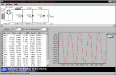
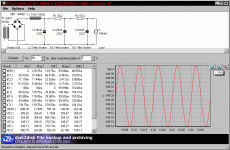
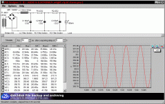
give me schematic of everything in front of Superreg - R , L, C values , and I'll calculate for you secondary voltage .
I know Superreg schematic from yore times of VS site , where parts of Superreg were published independently , so I just solved the puzzle ; later I bought books from Allen ;
but - what's most important - I made few of my own regs , including Shunty , which operate on same basic principles :
-series Mosfet demands just few volts more added to basic Ugs voltage ; LM317 needs few volts plus voltage sag across programming resistor
- shunt part of reg needs just programmed voltage across it , to be happy
all that - as bare minimum of in-out differential voltage , in moment when mains voltage is lowered for 10%
that's approx. just 50% of 15V I mention in my last post ;
Allen claimed for 50V as value which will cover even worst case scenario , saving him endless correspondence with ambitious , but not exactly up to task amateurs
just an observation - using CCS as in Shunty is better solution than using cascoded crummy LM317 ; I'm not saying that you'll hear diference , but from engineering point of view .....
I know Superreg schematic from yore times of VS site , where parts of Superreg were published independently , so I just solved the puzzle ; later I bought books from Allen ;
but - what's most important - I made few of my own regs , including Shunty , which operate on same basic principles :
-series Mosfet demands just few volts more added to basic Ugs voltage ; LM317 needs few volts plus voltage sag across programming resistor
- shunt part of reg needs just programmed voltage across it , to be happy

all that - as bare minimum of in-out differential voltage , in moment when mains voltage is lowered for 10%
that's approx. just 50% of 15V I mention in my last post ;
Allen claimed for 50V as value which will cover even worst case scenario , saving him endless correspondence with ambitious , but not exactly up to task amateurs
just an observation - using CCS as in Shunty is better solution than using cascoded crummy LM317 ; I'm not saying that you'll hear diference , but from engineering point of view .....
ok
if your goal is to have 300Vdc after Superreg , as needed for RTP3D .....
you can decrease programmed current in Superreg to some 100mA
load is approx. 19+14+15 mA (per channel) and going to anything more than twice that for programmed current is just waste
correct that , simulate again and correct needed values of resistors in RC chain
edit: with 420Vac and 100mA as load , you're spot on
Attachments
Last edited:
yes
no side effects, you only raise the voltage of the cathode and something 7 or 8 or 9 doesn´t matter
and my superreg runs with 330V Vin since 10 years
no side effects, you only raise the voltage of the cathode and something 7 or 8 or 9 doesn´t matter
and my superreg runs with 330V Vin since 10 years
Hi vtr,
Having read your comment on replacing the LM329 with a 9 Volt battery as a sonical improvement I wonder if that can be done without any other changes i.e. a LM329 de-
livers 6.9 Volt whereas your batteries will give 9 Volt. So are there no more changes
required? Thanks
Hi,
but:
I calculated: 19mA phono + 14mA cascode + 30mA follower == around 65mA
(so hopefully I was wrong with the 30mA...)
Then I knew the choke to be used with max. 160mA...
Therefore I got my values.
Are you calculating mono???
You're around 50mA / channel, twice is 100mA...
but:
I calculated: 19mA phono + 14mA cascode + 30mA follower == around 65mA
(so hopefully I was wrong with the 30mA...)
Then I knew the choke to be used with max. 160mA...
Therefore I got my values.
Are you calculating mono???
You're around 50mA / channel, twice is 100mA...
there is no way that Allen was using either 6DJ8 or Jfet at more than 10-12mA ... meaning that SLCF is drawing 20-24mA
when I wrote 15 , that was a typo , sorry .
find enclosed two sims - one for dual mono PSU ( one PSU and SR per channel ) , second one for common PSU for both channels (one PSU and SR for both channels)
of course that first version is preferred
when I wrote 15 , that was a typo , sorry .
find enclosed two sims - one for dual mono PSU ( one PSU and SR per channel ) , second one for common PSU for both channels (one PSU and SR for both channels)
of course that first version is preferred
Attachments
Once there are separate shunt regulators, one for each channel, I wonder howe much dual rectifiers and chokes would contribute.
yeah
diminishing returns ;
but certainly less headache , regarding possible ground loops - when you completely control where grounds of L & R channel will meet
IMHO: less money in your wallet, nothing else...Once there are separate shunt regulators, one for each channel, I wonder howe much dual rectifiers and chokes would contribute.
yeah
diminishing returns ;
but certainly less headache , regarding possible ground loops - when you completely control where grounds of L & R channel will meet
With separate shunt regulators, the HV+ are separated between the channels. On can add a capacitance multipliers, dropping say 10V, to the HV-, one for each channel. Thus the HV supply will be completely isolated between the 2 channels.
yup - positive and negative legs are certainly more than isolated through separate shunt regs (for positive ) and plain voltage regs (for negative ,even common for both channels ,due to isolation nature of CCS-es in cathodes) ;
but what I meant is strictly controlled galvanic separation of signal gnd between channels.
anyway , I'm speaking of that not as about sole possible way of doing it ; just trying to explain sort of purist approach , which Allen certainly had , when making of RTP3D is in question .
in any case - DIY-ing that sort of preamp is supposed to be a fun , when one if err - err on exaggerating side , not attempt in making something extraordinary for pocket money.
yup - positive and negative legs are certainly more than isolated through separate shunt regs (for positive ) and plain voltage regs (for negative ,even common for both channels ,due to isolation nature of CCS-es in cathodes) ;
but what I meant is strictly controlled galvanic separation of signal gnd between channels.
anyway , I'm speaking of that not as about sole possible way of doing it ; just trying to explain sort of purist approach , which Allen certainly had , when making of RTP3D is in question .
in any case - DIY-ing that sort of preamp is supposed to be a fun , when one if err - err on exaggerating side , not attempt in making something extraordinary for pocket money.
As far as I can see, my solution enables complete galvanic isolation between the 2 channels, with very little added cost (over 1 PSU and 2 shunt regulators).
If that suits you , OK by me .

Can you see any possible benefit by having dual PSU?
- Home
- Amplifiers
- Tubes / Valves
- Vacuum State RTP3C


