If anyone here in this thread would sell me his CD, I would be very happy...
Ditto - please PM me.
Thanks
Karl
Best +B PSU
I'm thinking of building on RTP3 or FVP5 préamp and I would like to know what kind of HT power supply to use.
I can't find any information about the vaccum state schematic.
Alex Megann says about the same in his DIY RTP3D :
The Vacuum State Electronics Realtime preamplifier
Is there a vaccum state schematic available ?
Or what could be the best +B PSU ?
Thank you
vince

RTP3D has choke in heaters as well. And MKP filtering.
Heaters are supplied by current sources. He uses 15V Transformers - I guess 9V is sufficient. B+ trafo is 340V, because of choke filter before caps and 60uF, 47 ohm CRC (3 Stages...)
Does anyone know a tool to simulate such supply? I don't want to solve differential equations...
Heaters are supplied by current sources. He uses 15V Transformers - I guess 9V is sufficient. B+ trafo is 340V, because of choke filter before caps and 60uF, 47 ohm CRC (3 Stages...)
Does anyone know a tool to simulate such supply? I don't want to solve differential equations...
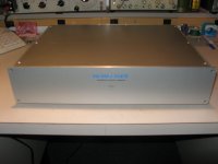
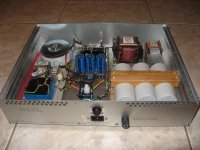
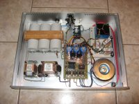
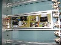
I've being building the RTP3C for some time now. This is the RTP3D Power supply version. I did my own cases design using Front Panel Express and metal profile for the sides. The 'D' version of the supply use the same polypropylene caps as the DPA300B amps, a pcb for all the other voltages than the HV that is still point to point. Choke filtering for both High and Low heater voltages. There is also CRCRC filtering in my case to match the HV to a correct value. I use Lundhall HV transfo and choke, Avel Lindberg toroid for the heaters and the smaller Telema for the +/-30V supplies. I also have a furutech AC inlet, separate fuse socket (to experiment with audio fuse if I want to try) and my own version of Ayre ES line filter.
All wires are solid copper solid core. PCB is my own design. It also contains a voltage selection switch (ala SVP2), ground loop breaking circuit, separate transfo fusing, HV delay timer/relay and the Heater voltages diodes and caps.
Parts choice is mostly my own, inspired by the SVP2 and what I read on the net.
The final version of the supply, that I adjusted with the completed preamp use now Dale chassis mounted resistors for the HV CRCRC, one bigger choke for the bigger the heater supply, DSEP12-12A HV FRED Diodes
Attachments
Last edited:
Just a few question:
You use a 160mA speced choke - I have a smaller 150mA Lundahl - ok???
How do you get the required HV? 250V + 48V = 300VAC. Is this sufficient choke before caps???
What MKP caps are you using? Motorcaps? Which source???
What is a ground loop braking circuit???
Regs, Dirk
You use a 160mA speced choke - I have a smaller 150mA Lundahl - ok???
How do you get the required HV? 250V + 48V = 300VAC. Is this sufficient choke before caps???
What MKP caps are you using? Motorcaps? Which source???
What is a ground loop braking circuit???
Regs, Dirk
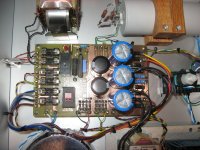
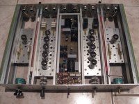
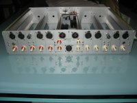
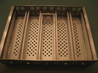
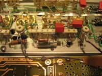
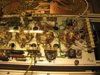
This is my actual preamp, almost completed. I still need to complete the phono in/out and preamp out wiring using VSE silver foil. I use for now my own version of the SuperReg and plane to add the 'No LM317' and AD797 mods to them.
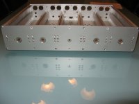
Again, casing is my own design. It was difficult to find the inside rails and make them fit all my hand assembly (More than 40 small holes to drill and tap on the 10 slides, then the smaller inside alu rail to old the preamp plates).
For the preamp plate I used the manual scaled images of the preamp, and match their size to the actual case. It fits almost perfectly.
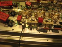
Again parts choice is inspired from the DPA300b (ceramic mounting strips, resistors) and discussion on various forum and other users. It was a lot of work to put together.
For the coupling caps I'm using the same caps as the SVP-2. They are used now in the newest 'D' version.
I also design a small PCB to contain the REC OUT and Timer/Mute circuits. It can be seen on the front of the preamp.
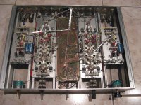
All wirings is done with solid silver plated copper small diameter wires for most of the inputs, except the phono that uses VSE silver foil and the first line input that use VSE silver wire.
Here a few pictures of the entire process...
Again, casing is my own design. It was difficult to find the inside rails and make them fit all my hand assembly (More than 40 small holes to drill and tap on the 10 slides, then the smaller inside alu rail to old the preamp plates).
For the preamp plate I used the manual scaled images of the preamp, and match their size to the actual case. It fits almost perfectly.
Again parts choice is inspired from the DPA300b (ceramic mounting strips, resistors) and discussion on various forum and other users. It was a lot of work to put together.
For the coupling caps I'm using the same caps as the SVP-2. They are used now in the newest 'D' version.
I also design a small PCB to contain the REC OUT and Timer/Mute circuits. It can be seen on the front of the preamp.
All wirings is done with solid silver plated copper small diameter wires for most of the inputs, except the phono that uses VSE silver foil and the first line input that use VSE silver wire.
Here a few pictures of the entire process...
Attachments
-
 RTP3_Preamp_Inside-2.JPG180.4 KB · Views: 991
 -
 RTP3_Preamp_Inside-1.JPG203.1 KB · Views: 1,546
 -
 RTP3D_Preamp_Sub_Panel.jpg72.9 KB · Views: 1,514
 -
 RTP3D_Preamp_Rear_Conn1.jpg101.7 KB · Views: 1,527
 -
 RTP3D_Preamp_Center_Section.jpg111.8 KB · Views: 1,546
 -
 RTP3D_Preamp_Inside_Tracks.jpg123.1 KB · Views: 1,615
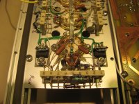
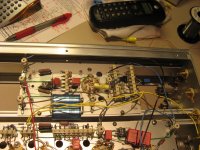
Some details of the preamp plates. Pictures are not from the completed preamp, but from the prototype stage. The final one has the nice wiring done.
Attachments
Last edited:
HVFanantic here response to your questions. Don't forget that I'm not using the original kits parts, so I had to adapt. I don't pretend either that my own supply is a perfect replica of the original, since I don't have the same irons.
You use a 160mA choke. I cannot comment, that was the closest to the original I found...
How do you get the required HV? The Lundhall LL1683 is dual 250V. Use them in serie and you have too much voltage") hence the need for the CRCRC filter to lower it.
hence the need for the CRCRC filter to lower it.
What MKP caps are you using? Motorcaps? Which source???
The big grey ones? Comar from Italy, impossible to source I guest. I got mine luckily from a vendor on ebay that had a few...
The original, as the DPA300B uses, have a mounting screw on them. Mine has not, so I had to devise a way to mount them, hence the oak mounting bracket. Sound probably better too, just kidding.
What is a ground loop braking circuit??? Original one use only one resistor between gnd and chassis. A better approach is to use a bridge, resistor and cap. See Earthing (Grounding) Your Hi-Fi - Tricks and Techniques for details
You use a 160mA choke. I cannot comment, that was the closest to the original I found...
How do you get the required HV? The Lundhall LL1683 is dual 250V. Use them in serie and you have too much voltage
hence the need for the CRCRC filter to lower it. What MKP caps are you using? Motorcaps? Which source???
The big grey ones? Comar from Italy, impossible to source I guest. I got mine luckily from a vendor on ebay that had a few...
The original, as the DPA300B uses, have a mounting screw on them. Mine has not, so I had to devise a way to mount them, hence the oak mounting bracket. Sound probably better too, just kidding.
What is a ground loop braking circuit??? Original one use only one resistor between gnd and chassis. A better approach is to use a bridge, resistor and cap. See Earthing (Grounding) Your Hi-Fi - Tricks and Techniques for details
All there is needed to know how to build a RTP3C, pictures, BOM,etc...
The CD is the instruction manual that comes with an RTP kit. You get one by buying an RTP kit.
And i believe that if you want the disk, you should buy the kit, otherwize you are abusing Allen (and his heirs) innellectual property (ie being a pirate)
dave
Dave, since you quote me: RTP3@Holger is mine and has serial number #22
The CD is the instruction manual that comes with an RTP kit. You get one by buying an RTP kit.
And i believe that if you want the disk, you should buy the kit, otherwize you are abusing Allen (and his heirs) innellectual property (ie being a pirate)
dave
- Home
- Amplifiers
- Tubes / Valves
- Vacuum State RTP3C