I haven't tried it, but Allen did. And he was ok with that. And his ears were much better than mine.I wanted to raise the same question to Thomas to hear if it could give a sonical advantage to increase the shunt current to much more than 15 mA although he said already that this is sufficient.
Looking at pictures from more recent RTP3's with the new Gen2 SR I see that VS has applied that already in the meantime.
Probably this has been done there only for better heat dissipation to stay much more on the safe side and not in order to go for much higher shunt currents I would assume.
The bigger heatsinks are indeed only there to prevent them from loosing their black colour.

They are still above 60°C, but an RTP will never run cool.
Filaments or heaters? I have always gone for calling them filaments. Don't ask me why?
As far as I have understood it so far, "filament" is used for direct heated tubes and "heater" for indirect heated ones...
Didn't Allen advocate setting the shunt current to the same as the series current delivered to the circuitry? I have never had the nerve to increase mine beyond about 20mA, especially considering the whole current is shunted on switch-on, when the heaters are cold and the valves aren't conducting.
Alex
Yes, that was the ideal situation, so that the regulator could supply the full current, in case it was needed. But, in practice, Allen suggested shunting ca. 20 mA.
Filaments or heaters? I have always gone for calling them filaments. Don't ask me why?
Isn't it one of those UK/US things? Although these days, after spending years on these international forums, I don't remember which way round it is...
Alex
Isn't it one of those UK/US things? Although these days, after spending years on these international forums, I don't remember which way round it is...
Alex
"Filament" was a term used for the glowing wire in the early lighting bulbs. As the first valve (later, "tube" in the US) evolved from this bulb and it was directly heated, the term "filament" for the cathode was maintained. Later, the indirectly heated cathode was devised. There, the cathode was no longer a wire (filament) but rather a metal surface which was warmed up with the aid of a separate heating wire, aka the "heater", in order to emit electrons. This is what I have learned after some decades of dealing with hollow state electronics. If I'm wrong, please forgive me.
If you want to make this preamp I have a pair of pcb available, making the build of it much easier, with full schematic and detailled parts list, see:
FS: Pair of RTP3 Platine Tube Preamp PCB
FS: Pair of RTP3 Platine Tube Preamp PCB
Attachments
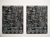
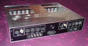
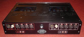
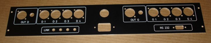
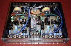
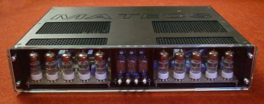
A few pictures of the original preamp using these pcb... You can see the rear using input selector pcb, the power transformers (I would mount them into a separate enclosure if it was me). The PCB will come with the original project files that I found. The front has three nixie tubes, they were used in the original project to display the source selection I think. I now nothing of this feature and they are not needed for the preamp.
SB
SB
Attachments
Last edited:
Hi guys,
I am planning to diy line-stage part of RTP3.
here at discussion was mentioned RTP3D version, even above PCBs are of this model - could be possible to get schematics for this circuit?
At VacuumState website is only RTP3C schematics and I am confused a bit how to properly set and supply points for current sources etc...
I would for this purpose maybe buy PCBs from you, Algar_emi, even if I have already AliExpress kit of "Hi-End AudioResearch ARC Tube Preamplifier Balanced/RCA IN&OUT,12AU7/ECC83+ECC88/6DJ8 Preamp DIY Kit" and I would rather modify (maybe.......) this kit to be somehow simiullar to RTP3D...
Thx, Jiri
Last edited:
Building the Vacuum State Electronics Realtime Preamplifier
The difference is the current source at high voltage side of the follower. So you have one tube less.
The difference is the current source at high voltage side of the follower. So you have one tube less.
Attachments
Last edited:
thank you.
do you mean it is realised vacum-tube currnent source at ver. RTP3D instead of resistor 25K which is seen at ver. RTP3C?
nevretheless, at link you posted (I already have seen this nice webpage) I could not find schematics of ver.RTP3D, all internal links of this page shows empty destinantions..
so - the need for RTP3D schematics is still here
Last edited:
One uses a mosfet as current source and the other a triode, that’s all. And indeed, the details can be found in his “cookbook”. If you do not understand the circuit and can not read schematics it is maybe unwise to start this project as it is not for beginners. (I hope you now try to prove me wrong and succeed in it! )
Best regards, Frank
Best regards, Frank
thank you, Guys. I would buy the Cookbook from VacuumState directly, but before a month or so I asked for some details and pricing cocnerning their products but I did not get any reply, so I am not sure if company works normaly or they have some covid limitations or there is some other isue.
Concerning the schematics, I am asking for detailed (RTP3D) circuit namely because at published RTP3C circuit are resistors at right of the output stage listed as 1m0 for example, which I guess is some value left from circuit simulation and do not reflect really needed values...
Simillary with all CSs, I can imagine some different types of CS circuitry, as I am able moreless to analyze the circuit, but not skilfull enough to make circuit synthesis.
Therefore I am seeking for real values used parts..
....I see CookBooks are available at e-shop, I have missed it from some vierd reason.. I am going to order it now.
....Ordered.
Last edited:

Shameless plugging ahead!) a book available that answers all your questions about this circuit and the current sources for it.
A really good read.
dave
Yes it is.
If you like reading about audio then there is an other book that could interest you:
“The search for musical ecstacy”
By Harvey Rosenberg “Gizmo”
Buy Dr. Gizmo's Book
If you like reading about audio then there is an other book that could interest you:
“The search for musical ecstacy”
By Harvey Rosenberg “Gizmo”
Buy Dr. Gizmo's Book
Last edited:
Look at this circuit (#1) even if it is not the same amp but the same output stage (Mosfet instead of tube).
I think quite a few people have been confused by the RTP3/RTP4/RTP5 progression over the years. The RTP3 is the differential preamp design that Allen would always recommend - I understand he originally thought the MOSFETs in the bootstrap and CCS locations in the '4 and '5 were a good idea, but eventually came to the opinion that the all-tube version sounded better. The RTP3C is the published circuit, and the one I built my own project from, and the RTP3D - as Thomas points out - has basically the same signal circuit, with a few changes in the PSU.
Alex
about light bulbs
Hi,
so i can clarify the myth about the lightbulb
i built an rtp 3 20 years ago and after some time the leds in the superreg died ( i use 3 phase tube rectifed power supply and no hv power delay circuit)
so my superreg has to take app. 60ma until the ecc88 tubes are operating, and they quit after 2 years their job.
my solution was to replace it with a small lightbulb (i think 80 or 100mA and 10 or 12V)
i told/showed this allen at a Triode Festival and since then its part of the superreg
thats all
greetings
Klaus
Hi Alex,
Having looked up again the photos of your Super Regs I also noticed a change VS obviously made in current production SR kits.
For visual control of operation they are using now a light bulb whereas in my older units LED's were applied.
Since dice45 pointed out that using an LED here is not the best way because this could result in a short-circuit in case of an overload or damage I would like to upgrade mines to bulbs as well.
Could you please tell me something more on this bulb applied here?
Is this an E10 bulb or other? And more important for me to know would be what voltage and current spec this light bulb has.
I would be happy if you could answer me this.
Thanking you in anticipation.
Günter
Hi,
so i can clarify the myth about the lightbulb
i built an rtp 3 20 years ago and after some time the leds in the superreg died ( i use 3 phase tube rectifed power supply and no hv power delay circuit)
so my superreg has to take app. 60ma until the ecc88 tubes are operating, and they quit after 2 years their job.
my solution was to replace it with a small lightbulb (i think 80 or 100mA and 10 or 12V)
i told/showed this allen at a Triode Festival and since then its part of the superreg
thats all
greetings
Klaus
- Home
- Amplifiers
- Tubes / Valves
- Vacuum State RTP3C