Direct heated triodes have low gm, 1,8mA/V for this one, not very suitable for cascode i`m afraid..
The first stage is extremely lightly loaded by the second stage. All it has to do is provide adequate stage gain with very little drive. A DHT should be perfect.
Shoog
Are you sure? Afaik, the upper stage can be seen as a common grid stage, wich has low input impedance.
I also remember reading (in the preamp cookbook?) an ideal cascode needs high gm in the lower tube
Are we talking about the same valve here. I am referring to the input valve which drives the middle tube of the SLCF. Since the middle tube is the CF its grid is high impedance and so the input valve is driving its high impedance and its own anode load, which should approximate to slightly less than the anode load.
Edit: I have just rechecked the schematic, and Allen has added a cascode in the first stage where previously there was only the single driver tube. As such you are correct. However if I built it I would only use a single triode in this position.
Shoog
Last edited:
Edit: I have just rechecked the schematic, and Allen has added a cascode in the first stage where previously there was only the single driver tube. As such you are correct. However if I built it I would only use a single triode in this position.
Shoog
Ok, now we understand eachother.
Another RTP3C builder
Hello folks,
Just a few days ago, I found this thread (in fact, I don't visit frequently the forum) and I decided to jump in, as I am an RTP3C builder and major fan of late Allen Wright.
Back in 1999, and after having read The Tube Preamplifier Cookbook a few times, I decided to go on building one of Allen's designs. My first AW project was an FVP5 (the early MOSFET version, not the later all-tube FVP5A version). I was so amazed by the sound of the preamp, that I said to myself that I had to build the all differential RTP3 preamp.
Since that was a project beyond my design skills, I had to purchase a full set of (then printed) manuals from Allen. I remember paying 200 Euros for the whole set. That was back in 2004. Later, Allen was selling the manuals in a CD form (for half the price) and was very kind to send me a copy of the CD, along with a set of matched RIAA capacitors and resistors without any extra charge.
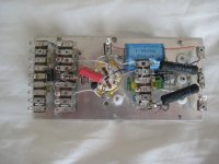
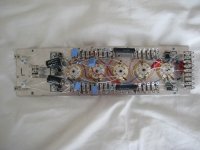
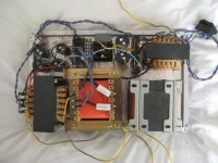
Meanwhile, I started to build the preamp from scratch, designing the cases, modules etc. Indeed, it was a quite difficult job. To make the long story short, it's been a long time now that I have finished most of the work, but, due to other projects always emerging, I never sat down to complete my RTP3C. In the following pictures you can see the phono and line modules.
Hello folks,
Just a few days ago, I found this thread (in fact, I don't visit frequently the forum) and I decided to jump in, as I am an RTP3C builder and major fan of late Allen Wright.
Back in 1999, and after having read The Tube Preamplifier Cookbook a few times, I decided to go on building one of Allen's designs. My first AW project was an FVP5 (the early MOSFET version, not the later all-tube FVP5A version). I was so amazed by the sound of the preamp, that I said to myself that I had to build the all differential RTP3 preamp.
Since that was a project beyond my design skills, I had to purchase a full set of (then printed) manuals from Allen. I remember paying 200 Euros for the whole set. That was back in 2004. Later, Allen was selling the manuals in a CD form (for half the price) and was very kind to send me a copy of the CD, along with a set of matched RIAA capacitors and resistors without any extra charge.
Meanwhile, I started to build the preamp from scratch, designing the cases, modules etc. Indeed, it was a quite difficult job. To make the long story short, it's been a long time now that I have finished most of the work, but, due to other projects always emerging, I never sat down to complete my RTP3C. In the following pictures you can see the phono and line modules.
Attachments
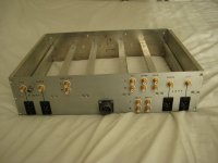
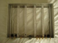
Here are the pictures of the chassis. All work is done by hand. The most difficult part of the (mechanical) work was marking, drilling and tapping tenths of holes.
I have yet to add a couple of XLR connectors...
I have yet to add a couple of XLR connectors...
Attachments
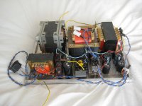
And here is the power supply. I have already tested it, but I have to change the connection of the choke. I remember Allen saying somewhere that, for a choke input filter and a higher than average voltage, it is much more safe for the choke to connect it to the ground, rather than the positive rail of the PS filter, since the AC ripple is very high and could possibly damage the choke's insulation (except for when the choke is specifically designed and constructed for a choke input filter, but I doubt that mine is).
Attachments
From your pictures, you were pretty close! That looks like a great job.
Alex
Thanks Alex. I know I'm pretty close, but I have to commit myself to finishing it.
We had exchanged a couple of messages some time ago, I think it was regarding Emille Sprenger's shunt regulator. No, I'm not using it, I have already built Allen's SuperRegs for the RTP3C.
Evangelos
P.S. what has happened to your site? It seems to be down for the last days.
Current Sourced Filaments
Here is an issue with RTP3C and I'm addressing my comment and question to all RTP3C builders:
In the past, Allen was a great supporter of the concept of current sourced filaments and that's how this was implemented in the original RTP3C manual. But, later, I read a post of his in Audio Asylum regarding this issue. His post was the following:
You may get interesting results. Our RTP3C preamp originally used CCS fed Russki 6H23phi's - untill we found that even with an almost perfectly idential current, some lit up like light bulbs, but in others you couldn't see any glow even in a dark room. The V across each tube reflected their "brightness - ranging from about 5.2V to over 7! (when all fed with 300mA).
Replacing them with Japanese made 7DJ8's which are intended for series heaters, everything evened out, and rewiring the Russki's to regular 6.3V fed heaters also evened things out,
So watch out...
Regards, Allen
Here is the entire thread:
Current Source Filaments
I have already wired the filament to be fed by LM317 as current sources for each tube. Since I too will use the "Russkies" 6N23P-EVtubes, I'm worried about this. Of course, first of all, I will test each one off-board to check its filament voltage when fed from a 300 mA CCS. But, if voltage is high, what would be a good idea for changing from CCS to CVS? Modifying the LM317 for a 6.3 V regulator would be complicated and would require a lot of components and work. Using a 7806 regulator seems much simpler and easier to me. What are your experience and suggestions?
Evangelos
P.S. what has happened to your site? It seems to be down for the last days.
The University server, which hosts my pages, is down for maintenance this week. It should be back up at the weekend!
Alex
Here are the pictures of the chassis. All work is done by hand. The most difficult part of the (mechanical) work was marking, drilling and tapping tenths of holes.
I have yet to add a couple of XLR connectors...
Hi Evangelos,
What connectors did you use for power input? They look very similar to the Amphenol C016 ones I used.
I notice that you have "Rec out" sockets on your back panel. Do you have any extra buffering for these outputs? I used OPA604 op-amps (I never told Allen
") ) for this, since the phono EQ in particular is very sensitive to loading.
) for this, since the phono EQ in particular is very sensitive to loading.Finally, how did you print the text on the rear panel? It looks very professional.
Alex
Hi Evangelos,
What connectors did you use for power input? They look very similar to the Amphenol C016 ones I used.
The connector I have used is Amphenol MS3102A16S-1P. Like this:
Amphenol - MS3102A16S1P
I notice that you have "Rec out" sockets on your back panel. Do you have any extra buffering for these outputs? I used OPA604 op-amps (I never told Allen
I will use a very simple jfet (2sk170) source follower, that Allen has in the manual. But rather with an active current sink (another 2SK170).
Finally, how did you print the text on the rear panel? It looks very professional.
Whether you believe it or not, this is the all times classic Lettraset with a coat of clear varnish to prevent chipping.
I think it is similar to what I used, although I went for a completely dual mono PSU, and therefore dual power connectors.
Whether you believe it or not, this is the all times classic Lettraset with a coat of clear varnish to prevent chipping.
It does look good! You have inspired me to try Letraset on mine.
Just a note on the RTP3 - Allen always told me that he thought his preamps need to be left powered up continuously, otherwise one would get no idea of the performance they were capable of. A couple of weeks ago I finally changed to leaving mine on permanently, instead of switching on a couple of hours before listening sessions, and the difference is shocking. I now understand why the RTP3D is supplied with no mains switch
Alex
6,3 Volt heaters
Vtr,
Ok, I can understand that the CCS heater current supply can be made individually adjustable with pots rather than using fixed resistors. However how did you get the 6.3 Volt since as far as I know the heater supply in the RTP3 delivers 12 V as coming from the power supply? Did you make then the whole heater supply 6.3 Volt or did you do it individually per tube? Thanks
airtangent
i had the same issue and i made all my heater ccs trimmable for soma ma´s and then trimmmed each to 6,3 v. i know its some hassle with tube rolling but everything is a compromise....
Vtr,
Ok, I can understand that the CCS heater current supply can be made individually adjustable with pots rather than using fixed resistors. However how did you get the 6.3 Volt since as far as I know the heater supply in the RTP3 delivers 12 V as coming from the power supply? Did you make then the whole heater supply 6.3 Volt or did you do it individually per tube? Thanks
airtangent
I suppose this is done individually for each tube, trimming the ccs to give 6.3 V on the filament. That means, for a voltage of 6.3 V, a tube may need a current of 300 mA and another 310 mA. Hence, you adjust the current through the filament that develops the desired voltage on it.
i had the same issue and i made all my heater ccs trimmable for soma ma´s and then trimmmed each to 6,3 v. i know its some hassle with tube rolling but everything is a compromise....
You mean with a trimmer in parallel with a resistor between the ADJ and OUT pins of LM317? What are the values you used?
I certainly did not find the same with mine. There was no need to warm it beyond an hour.A couple of weeks ago I finally changed to leaving mine on permanently, instead of switching on a couple of hours before listening sessions, and the difference is shocking. I now understand why the RTP3D is supplied with no mains switch
Alex
Ridiculous waste of tube life to leave it running permanently.
- Home
- Amplifiers
- Tubes / Valves
- Vacuum State RTP3C