1st This is an old board. Not all 550s worked with all relays so we moved to BC517 or 100nF C-B capacitor. Zener is an OK fix too, tried and tested.
2nd Yes that was deliberate and it has to do with voicing a particular THD profile when running low current in the regs as it was meant to can work without heatsinks even.
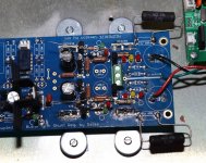
It must be running about 60mA per rail as shown in the photo. 200mA extra than max consumption is advised for 1st stage hot-rod dcb1 or any other general purpose powering.
If you had read post#1 you would have seen the leg trick that restores symmetry for general reg use or hot-rod dcb1 use, as well as a practical guide on how to scale the Vo.
3rd. 10mV is out of spec. Up to 5mV can be tolerable but we usually see 0.5-1.2mV offset reports in the Hypno Hot-Rod with matched JFETs often sourced from minikits.
Restore 2nd in case it helps the offset thing too. If not enough then the K170s signal quad needs rematching. Or just the pair in the bad channel, but with similar idss to the other channel.
2nd Yes that was deliberate and it has to do with voicing a particular THD profile when running low current in the regs as it was meant to can work without heatsinks even.
It must be running about 60mA per rail as shown in the photo. 200mA extra than max consumption is advised for 1st stage hot-rod dcb1 or any other general purpose powering.
If you had read post#1 you would have seen the leg trick that restores symmetry for general reg use or hot-rod dcb1 use, as well as a practical guide on how to scale the Vo.
3rd. 10mV is out of spec. Up to 5mV can be tolerable but we usually see 0.5-1.2mV offset reports in the Hypno Hot-Rod with matched JFETs often sourced from minikits.
Restore 2nd in case it helps the offset thing too. If not enough then the K170s signal quad needs rematching. Or just the pair in the bad channel, but with similar idss to the other channel.
With steady mains 12VACx2 is enough. It was the historically first recommended Tx so not to push the naked MOSFET CCS thermally when used in the low current mode. Many people used DCB1s in low current with no sinks, the quality was deemed adequate. Hot-Rod* was a fad started a little later. But some people actually use them like that still in integrated amps with no space for hot-rod. If using sinks 15-0-15V is even better. In Rudi's pic the CCS have very small sinks, probably the original builder had lively mains or a bit overshooting Tx. That board must be 6-7 yrs old issue.
*The small bridge diodes are not reliable for over 250mA constant current. All those things are addressed in the DCB1 Hot-Rod version anyway that circulates for many years now.
*The small bridge diodes are not reliable for over 250mA constant current. All those things are addressed in the DCB1 Hot-Rod version anyway that circulates for many years now.
I have replaced the 2SK170 transistors of the "faulty" channel by two 2SK170GR - type of transistors, matched at Vgs = 0.4V and Iq = 5,51mA .
The channel has now a DC-offset of 0.1 - 0.2 mV !
I measured the transformer's (rated at 2 x 12VAC / 2 x 25 VA) secondaries.
They show 13VAC!, and everything works as designed.
Best regards - Rudi_Ratlos
The channel has now a DC-offset of 0.1 - 0.2 mV !
I measured the transformer's (rated at 2 x 12VAC / 2 x 25 VA) secondaries.
They show 13VAC!, and everything works as designed.
Best regards - Rudi_Ratlos
Pass DIY Addict
Joined 2000
Paid Member
Hi Salas, I'm working my way through re-purposing my blue Mez board as a regulated power supply for a preamp and am running into some strange issues with output voltage and current. The PSU going to the board provides +/- 37VDC. I was hoping you could shed some insights
On the Positive rail side (moving from PSU to Relays) I have the following measurements:
Current Set Resistor (2x68R position), I have a 4R power resistor that drops 1.42v to provide 355mA current to the first Mosfet
First 9240: G=32.4v, D=28.4v, S=36.5v
2SK170 next to 3-terminal AC input: S=0.9v, G=0.9v, D=32.4v
Vset LEDs + resistor: used a 1k6 resistor to provide ~27.5v output from regulator, this resistor drop 23.7v across it.
Second 9240: G=24.2v, D=0.0v, S=28.0v
2SK170 adjacent to second 9240 mosfet measures: S=25.9v, G=25.9v, D=30.9v
10R at the board output measures 0.13V for bias of 130mA
---------------------------------------------
On the Negative Rail Side, I have
Current Set Resistor (2x68R position), I have a 4R power resistor that drops 1.43v to provide 357mA current to the first Mosfet
First 240: G=-32.4v, D=-29v, S=-36.5v
2SK170 next to 3-terminal AC input: S=-32.3v, G=-32.3v, D=-0.8v
Vset LEDs + resistor: used a 3k3 resistor to provide ~-28.1v output from regulator, this resistor drop 22.8v across it.
Second 240: G=-24.5v, D=0.0v, S=-28.6v
2SK170 adjacent to second 240 mosfet measures: S=-32.3v, G=-32.3v, D=-0.8v
10R at the board output measures 0.05V for bias of 50mA
--------------------
Blue PP caps are mounted to the bottom of the board in the place where the 100uF caps are open on top.
So, there are two things going on that I don't understand.
1) Why do I need to use two different Vtest Resistor values (1k6 for pos and 3k3 for neg) to balance the regulator output?
2) Why am I getting two different bias levels at the 10R output resistors (130mA Pos and 50mA Neg)?
Attachments
Last edited:
Hi Eric
I think that the two K170s placed next to those 10R resistors have very different IDSS. Because those are the ones that define the current through the Vset LEDS and resistors, then its expected to need so different resistors in value if that's the case. Blue board needs no "leg trick" by the way.
Verify their IDSS and find nearer characteristics pair if you got any spares. If not, you may keep equalizing the voltage drops with different value Vset resistors.
Use the 100uF voltage reference filter capacitors also on top if the preamp is sensitive for noise. If medium to high gain analog or having some digital chips on it for instance.
Pass DIY Addict
Joined 2000
Paid Member
Thanks for the input, Salas. Those jFets are the unmatched ones, so they were probably just chosen at random because they didn't match any others that I had. I have no idea how they actually measured, I'll have to go back and see if I made any notes.
Sounds like everything is functioning correctly, and this is just a function of the parts I've used.
Sounds like everything is functioning correctly, and this is just a function of the parts I've used.
Salas
I have a problem with one half of Hypnotize regulator
problem Is voltage drop over Rset - at first, when started everything Is normal - I measure around 1.8 V over Rset but after 2 min of working voltage Is around 8 V and resistors and pcb will start to melt If I not turn off power
for Rset I use three 33R In parallel
would you please recommend what can cause that problem
")
- Status
- This old topic is closed. If you want to reopen this topic, contact a moderator using the "Report Post" button.
- Home
- Amplifiers
- Power Supplies
- Using the HYPNOTIZE as a general shunt reg PCB