Odd, I use the Silver Mica and found it very extended and transparent, but still as sweet as honey, not at all aggressive.
I do use big ML Monolith III ESL's. Sometimes with a Magnat MP-02 Plasma super tweeter from 10khz up, in Summer with the window open, to let the Ozone gas out.
Cheers George
I do use big ML Monolith III ESL's. Sometimes with a Magnat MP-02 Plasma super tweeter from 10khz up, in Summer with the window open, to let the Ozone gas out.
Cheers George
Filtering...
Very interesting. I would avoid ceramic types. The reason is they tend to ring under impulse. Not knowing more about your system it is hard to make any suggestions. I am using a Wima Polypropylene on my triple stack with the PCM1704. 470 pF as I recall. The PCM1704 is very well behaved where conversion noises are concerned. On my TDA1541 based stuff I am using Polystyrene capacitors of good quality. 1n8 again from memory. Silver Mica probably would work as I remember it is a very stable dielectric. Has a high Q factor. I think maybe the AD1862 has more conversion noise then is usually the case.Hi
I just want to share that I tried a few different types of caps for HF filtering with the ad844 i/v including silver mica, philips polystyrene, wima fkp. After all I found that c0g capacitor sound the most natural. silver mica sounds aggressive on top end. polystyrene emphasis upper midrange. wima fpk is a bit tight. Just my experience with this particular i/v stage.
COG ceramics are known not to ring under impulse - that is what they are good at. There are various kinds of ceramic cap and many are terrible for audio, but COG are known to be good. Bateman's capacitor articles explain it well Cyril Bateman's Capacitor Sound articles | Linear Audio NL
Hi Quan Tran,
Thanks for the info. Last night,I tried 1000pf silver mica and I kind of like it. On my system, it's not aggressive at top end, but a little thinner on mid to high tone. This could be the effect of lowering the capacitance. (It was 1500pf before) BTW, I solved the thermal issue of AD844. Instead of +-13.6V, +-5V solved the problem nicely.
Thanks for the info. Last night,I tried 1000pf silver mica and I kind of like it. On my system, it's not aggressive at top end, but a little thinner on mid to high tone. This could be the effect of lowering the capacitance. (It was 1500pf before) BTW, I solved the thermal issue of AD844. Instead of +-13.6V, +-5V solved the problem nicely.
COG Caps

Thanks for the information. Always nice to learn something new. Although my personal bias would steer me away from any ceramic in favor of the PPS, Polypropylene or Polystyrene. It is nice to know COG's could be used if need be.COG ceramics are known not to ring under impulse - that is what they are good at. There are various kinds of ceramic cap and many are terrible for audio, but COG are known to be good. Bateman's capacitor articles explain it well Cyril Bateman's Capacitor Sound articles | Linear Audio NL
AD844's
I have used + and - 12 VDC with the AD844's. That reduces heating somewhat. I believe the slew rate is slower at the + and - 5 VDC setting. If your happy with it and it is working well enjoy it. The Silver Mica cap probably needs some time in circuit to sound it's best.Hi Quan Tran,
Thanks for the info. Last night,I tried 1000pf silver mica and I kind of like it. On my system, it's not aggressive at top end, but a little thinner on mid to high tone. This could be the effect of lowering the capacitance. (It was 1500pf before) BTW, I solved the thermal issue of AD844. Instead of +-13.6V, +-5V solved the problem nicely.
I know ceramic caps sound scary to many. However c0g caps are totally different from the rest of the ceramic types. I appears to me that many good cdps and dacs now use c0g cap for Filtering the hf noise. I also suspect about them at first.
I am not saying that other caps mentions above are inferior. c0g caps measure well and they sound nice too.
I am not saying that other caps mentions above are inferior. c0g caps measure well and they sound nice too.
COG ceramics are known not to ring under impulse - that is what they are good at.
no ringing under impulse is exactly the point! when a capacitor is ringing it shows some signature in the sound.
Resistors
I am surprised that could be heard. I always use low TCR metal films in that position. It makes sense that a noisy resistor there might impart a sonic signature. Power rating... Well you only have 2 mA in that current source so 1/4 Watt should be fine. Never hurts to experiment. That is how we learn in our DIY quests.1k resistor in the current source circuit with 2sk170 - we should use good one. previously I used basic dale ccf, not so good :-( I have changed to KOA, much cleaner sound. higher power rating may be better.
I have used + and - 12 VDC with the AD844's. That reduces heating somewhat. I believe the slew rate is slower at the + and - 5 VDC setting. .......
I was wondering if the AD844 could work on +/- 5V in a mobile battery DAC?
The data sheet indicates slew rate is over 1000uv/s which seems like a 1000x safety margin assuming we only need 20kHz sine waves at 2Vrms (http://www.radio-electronics.com/info/circuits/opamp_basics/operational-amplifier-slew-rate.php)?
I was more worried about the output voltage limit on +/- 5V which seems to be <2Vp-p output which is only good for 1.4Vrms. Then again most amps seem to need even less volts in for full power.
If +/- 5V supplies provide sufficient operational overhead with minimal power use and thermal loading then why bother running higher voltages in transformer powered DAC's with +/- 5V regulated supplies available?
Any expert opinions are welcome please regards limits for the AD844 running off +/- 5Vsupplies and the ideal input volts.
AD844 opinion...
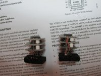
You could try it. The issue as I see it is the AD844 is current limited in the current mirrors. So running at minimum supply rails will likely be a handicap. The beauty of DIY is there is no reason not to give it a go. Build it and see if you think it meets your expectations. Die heating was likely the design constraint and why the current mirrors run so lean. In my triple stack I choose to build it with the SOIC 16 package. The larger die in my mind means less heating. Here is an example of my solution. For practical reasons I keep my rails at + and - 12 VDC.I was wondering if the AD844 could work on +/- 5V in a mobile battery DAC?
The data sheet indicates slew rate is over 1000uv/s which seems like a 1000x safety margin assuming we only need 20kHz sine waves at 2Vrms (http://www.radio-electronics.com/info/circuits/opamp_basics/operational-amplifier-slew-rate.php)?
I was more worried about the output voltage limit on +/- 5V which seems to be <2Vp-p output which is only good for 1.4Vrms. Then again most amps seem to need even less volts in for full power.
If +/- 5V supplies provide sufficient operational overhead with minimal power use and thermal loading then why bother running higher voltages in transformer powered DAC's with +/- 5V regulated supplies available?
Any expert opinions are welcome please regards limits for the AD844 running off +/- 5Vsupplies and the ideal input volts.
Attachments
I know ceramic caps sound scary to many. However c0g caps are totally different from the rest of the ceramic types. I appears to me that many good cdps and dacs now use c0g cap for Filtering the hf noise. I also suspect about them at first.
I am not saying that other caps mentions above are inferior. c0g caps measure well and they sound nice too.
You are right. C0G/NP0 are better here! I do have a bunch of TDK 1000pf NP0 from previous project. I replaced the silver mica with them and they do sound better!(more neutral, smoothness on mid to HF) It's hard to believe those inexpensive, tiny smd caps can have better sonic performance than big bulky silver mica or foil caps. I'd also recommend people to try C0G/NP0 ceramic here.
Caps...
For decoupling a TDA1541 I really like the surface mount PPS capacitors. They can be large even in surface mount. It is a matter of using the correct part for the purpose. Will keep COG's in mind for space limited applications.You are right. C0G/NP0 are better here! I do have a bunch of TDK 1000pf NP0 from previous project. I replaced the silver mica with them and they do sound better!(more neutral, smoothness on mid to HF) It's hard to believe those inexpensive, tiny smd caps can have better sonic performance than big bulky silver mica or foil caps. I'd also recommend people to try C0G/NP0 ceramic here.
For decoupling a TDA1541 I really like the surface mount PPS capacitors. They can be large even in surface mount. It is a matter of using the correct part for the purpose. Will keep COG's in mind for space limited applications.
What are the brand and voltage rating of the pps cap that you used with tdq1541a? I found some Panasonic PPS caps but the voltage rating is only 50V. For film cap higher voltage rating usually sound better to my ear but I don't have experience with PPS cap before.
Decoupling caps
Yes, I use the Panasonic 50 Volt PPS capacitors for decoupling. The current dividers have low voltages in them so 50 Volts is quite adequate. Even the 16 Volt parts would work here. PPS has a very nice sound. To my ear better then Polypropylene. As is always the case that is just an opinion. EC Designs in his thread uses an equal weighted dac current scenario. So the biggest caps are on the MSB and progressively smaller values as you reach the higher decoupling positions. I'd have to look that up if your interested. So far I have found that to be the best decoupling scheme I have used. I have free standing pins with a daughter board under the 1541 so the caps are all mounted under the chip.What are the brand and voltage rating of the pps cap that you used with tdq1541a? I found some Panasonic PPS caps but the voltage rating is only 50V. For film cap higher voltage rating usually sound better to my ear but I don't have experience with PPS cap before.
Decoupling caps
Yes. Sourcing all those values is likely tough. I used Mouser Electronics and they had what I needed. You could just use 0.1 uF in all positions. Philips original datasheet value will work. The advantage of the weighted dac currents only shows itself when the I/V is working at a very high level. Pretty much have to have everything optimized. My Mark II dac took 2 years of experiments to really show it's reference worthy ability. A SAA7220 digital filter will make it impossible to reach a "reference component level" in my experience.I will give it a try but it's difficult to source all the different value as recommended by ecdesigns
Digital filter thread for SAA7220 alternative
http://www.diyaudio.com/forums/digi...rnative-saa7220-tda1541-dacs.html#post4686124
http://www.diyaudio.com/forums/digi...rnative-saa7220-tda1541-dacs.html#post4686124
The data sheet indicates slew rate is over 1000uv/s which seems like a 1000x safety margin assuming we only need 20kHz sine waves at 2Vrms (http://www.radio-electronics.com/info/circuits/opamp_basics/operational-amplifier-slew-rate.php)?
Slew rates coming out of DAC chips are far, far in excess of the normal range for bandlimited (<=20kHz) audio. Right out of the DAC chip itself they do indeed run into V/nS - this being prior to band-limiting.
If +/- 5V supplies provide sufficient operational overhead with minimal power use and thermal loading then why bother running higher voltages in transformer powered DAC's with +/- 5V regulated supplies available?
A very good question, one I've asked myself a few times and not come up with a satisfactory answer so far. Maybe just tradition? I can definitely see value in running higher if a transformer is used to step down the voltage right before the output. But precious few DACs have one of those.
- Home
- Source & Line
- Digital Line Level
- Using the AD844 as an I/V