I am thinking about using this on a TDA1545A that has a DC offset of about 3.3V when running from 5V supply (it is a single supply DAC with the reference voltage created by a resistor divider).
The 'offset' for the TDA1545A is fairly flexible in that it can be set between 2 and 4 volts for a 5V supply. For a DAC where the offset can be set to 0V, check out the TDA1387 - its very similar to the 1545A, except runs on I2S.
The 'offset' for the TDA1545A is fairly flexible in that it can be set between 2 and 4 volts for a 5V supply. For a DAC where the offset can be set to 0V, check out the TDA1387 - its very similar to the 1545A, except runs on I2S.
Well as it goes I already have a working setup with the TDA1545A using OPA627's as IV converters and I was wondering if the AD844 IV circuit described in this thread could be used with such a high DC offset to replace them. I am not planning on changing the DAC any time soon.
The reference can be indeed changed between 2 and 4 volts but as I have it in the datasheet spec that's why I mentioned 3.3V. The question still remains the same - instead of DC offset in millivolts can AD844 IV be used in a 2 to 4V offset configuration with 1mA DAC current.
Hi,
I´m soo tired .... just soo tired ...
now I have to destroy the blabla-people´s -sorry, meant the marketing department´s- initial rave about the invention of the first complex devices that don´t generate phaseshift, the ´real´inductor and the ´real´ capacitor.
I´m soo tired.
jauu
Calvin
I´m soo tired .... just soo tired ...
now I have to destroy the blabla-people´s -sorry, meant the marketing department´s- initial rave about the invention of the first complex devices that don´t generate phaseshift, the ´real´inductor and the ´real´ capacitor.
I´m soo tired.
jauu
Calvin
The question still remains the same - instead of DC offset in millivolts can AD844 IV be used in a 2 to 4V offset configuration with 1mA DAC current.
If you're referring to the open loop configuration with output taken from pin5 I've not tried that myself. I have used AD844 with success in an 8*TDA1387 DAC in the 'standard' configuration with feedback. Points of note are that I needed CCSs (to the input to remove DC offset, on the output to bias the chip into classA) and that the feedback cap which is commonly used with VFB opamps (shown as C1,C2 in fig1 of the TDA1545A DS) must be removed.
Hi,
I´m soo tired .... just soo tired ...
Well, at least I tried to be civil about it.
Think positive, try think the best about other people. Less nitpicking and you will freshen up. I have had a great week, nothing is going going to dim that.
Notice I said zero 'current' phase angle as no load can change it - to nitpick back in my own defense.

Relax, OK.
Off to bed.
Cheers, Joe
Well, at least I tried to be civil about it.
Think positive, try think the best about other people. Less nitpicking and you will freshen up. I have had a great week, nothing is going going to dim that.
Cheers, Joe
People here have been civil now for 57 pages worth of posts talking about, and the utilization and sound of the AD844
Please start your own thread so I then can highjack it and turn it into a s**t fight for you.
Cheers George
Last edited:
Well as it goes I already have a working setup with the TDA1545A using OPA627's as IV converters and I was wondering if the AD844 IV circuit described in this thread could be used with such a high DC offset to replace them. I am not planning on changing the DAC any time soon.
The reference can be indeed changed between 2 and 4 volts but as I have it in the datasheet spec that's why I mentioned 3.3V. The question still remains the same - instead of DC offset in millivolts can AD844 IV be used in a 2 to 4V offset configuration with 1mA DAC current.
Hi Olev,
No problem for an input voltage offset. You simply have to tie pin 3 to whatever your voltage reference is. Of course, it must be within the AD844 common input range limits, which is specced -10/+10V for +/-15v psu.
The 2sk170 current source used with tda1541 is not for voltage offset nulling of the ad844, but for current offset nulling of the dac, which would cause an imbalance in the ad844 if fed directly.
People here have been civil now for 57 pages worth of posts talking about, and the utilization and sound of the AD844
Please start your own thread so I then can highjack it and turn it into a s**t fight for you.
Cheers George
George, you have a problem - go see somebody who can help you.
Hi apolon34,
Thanks for clarifying the 2sk170 misunderstanding and clarifying the pin 3 tieing. So it will basically use the same input as a regular opamp with the dac output current fed to inverting and the reference voltage fed to the non-inverting input.
How will AD844 keep the output offset? With OPA627 the output offset is about 2.18V with 3.3V input offset. I have not yet understood how this is explained exactly, the feedback is 5.6k so at 1mA DAC current the voltage swing will be 5.6V from the opamp (which works out to be 2V rms audio output). But why does it "idle" at 2.18V I don't have an explanation yet, why not 3.3V as the input, is this a voltage drop from some internal part of the OPA627? Will I expect the same from the AD844?
Hi apolon34,
Thanks for clarifying the 2sk170 misunderstanding and clarifying the pin 3 tieing. So it will basically use the same input as a regular opamp with the dac output current fed to inverting and the reference voltage fed to the non-inverting input.
How will AD844 keep the output offset? With OPA627 the output offset is about 2.18V with 3.3V input offset. I have not yet understood how this is explained exactly, the feedback is 5.6k so at 1mA DAC current the voltage swing will be 5.6V from the opamp (which works out to be 2V rms audio output). But why does it "idle" at 2.18V I don't have an explanation yet, why not 3.3V as the input, is this a voltage drop from some internal part of the OPA627? Will I expect the same from the AD844?
If you set the TZ resistor of the AD844 (as we use it with no global feedback) to give the same gain as you are getting from your OPA627, then yes the dc offset will be the same, as the TDA1541 and also I believe the TDA1545 have large amount of dc from their output.
I don't think you will be able to zero it out using pins 1 and 8 with the 20kohm trimpot on the AD844 it may not have the range.
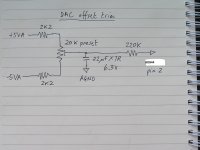
You could however use Abraxalitos dc nulling circuit (attached) after the dac to null it before it gets to the AD844 it may give better range, than just using pins 1 and 8.
Cheers George
Attachments
But why does it "idle" at 2.18V I don't have an explanation yet, why not 3.3V as the input, is this a voltage drop from some internal part of the OPA627? Will I expect the same from the AD844?
If you study the TDA1545A datasheet you'll note that the DAC contains two current sources - one is fixed (714uA, to the 5V rail) and the other's digitally controlled (0 - 1mA to GND). Thus when no music is playing the net result of these two is that 214uA comes from the 5V rail and thus reduces the opamp's output by this current multiplied by the resistor's value. As you have 5k6 you get 5.6*0.214 = 1.2V. This is subtracted from the 3.3V giving you 2.1V.
Hi apolon34,
Thanks for clarifying the 2sk170 misunderstanding and clarifying the pin 3 tieing. So it will basically use the same input as a regular opamp with the dac output current fed to inverting and the reference voltage fed to the non-inverting input.
How will AD844 keep the output offset? With OPA627 the output offset is about 2.18V with 3.3V input offset. I have not yet understood how this is explained exactly, the feedback is 5.6k so at 1mA DAC current the voltage swing will be 5.6V from the opamp (which works out to be 2V rms audio output). But why does it "idle" at 2.18V I don't have an explanation yet, why not 3.3V as the input, is this a voltage drop from some internal part of the OPA627? Will I expect the same from the AD844?
With a "classical" opamp, at equilibrium, the following rule apply:
VIn+ = VIn-
Therefore, if Vin+ is 3.3v, Vin- is 3.3v also. Then you can check which value should the input have in order to fullfill this conditions.
If you have a resistor between out and -in, assuming no current flows in, then vout = vin- = vref.
If it is different, then there is some current flowing at idle in the feedback resistor, caused by the current offset of the dac. In your case, it is stated at 714uA typical for the tda1545. This is not in accordance to the offset you measured, I don't know why. (edit: abraxalito gave the answer above)
Now, for the ad844 running open loop, the in+ = in- still applies but the rule to follow is current at TZ = current into In-.
If current into In-= 0 then current at TZ=0 and thus no DC offset in the R I/V going to ground (since no current).
In your case, you will need a current nulling servo if you want to DC couple the output.
Last edited:
With a "classical" opamp, at equilibrium, the following rule apply:
VIn+ = VIn-
Now, for the ad844 running open loop, the in+ = in- still applies but the rule to follow is current at TZ = current into In-....
George, am I allowed to comment on this?
If you study the TDA1545A datasheet you'll note that the DAC contains two current sources - one is fixed (714uA, to the 5V rail) and the other's digitally controlled (0 - 1mA to GND). Thus when no music is playing the net result of these two is that 214uA comes from the 5V rail and thus reduces the opamp's output by this current multiplied by the resistor's value. As you have 5k6 you get 5.6*0.214 = 1.2V. This is subtracted from the 3.3V giving you 2.1V.
Sorry for going offtopic, buy just to verify that I got it, is this how the TDA1545A works with ideal spec specifications?

Now, for the ad844 running open loop, the in+ = in- still applies but the rule to follow is current at TZ = current into In-.
If current into In-= 0 then current at TZ=0 and thus no DC offset in the R I/V going to ground (since no current).
In your case, you will need a current nulling servo if you want to DC couple the output.
This is right on the dot, but don't forget that even with the current into pin 2 being zero, the current at Tz is not perfectly zero. There is always a small offset current which will give a small offset voltage. Don't know how much, should be in the data sheet.
You can null that out by a small offset correction current into pin 2, or a small offset correction voltage to pin 3. Or using the offset control pins. Or a small offset correction current at pin 5 ;-)
Jan Didden
Last edited:
This is right on the dot, but don't forget that even with the current into pin 2 being zero, the current at Tz is not perfectly zero.
That's the comment I would have liked to have made, but seems George won't let me. I have measured that current. I am humble enough to ask this question, if you null Pin 6 out, then there won't be an exact null on Tz, and vice versa. We know that global fb sorts that out. I have assumed this difference is due to the buffer not being inside the loop as we are eschewing f/b. But would what you just stated "the current at Tz is not perfectly zero" and I do indeed agree with that, does it have a bearing here? No global f/b and the buffer does its own thing, right?
Cheers, Joe
PS: George, this is a public forum on a topic that does interest me - my number of posts out of 1000+ hardly constitutes me wanting to take it over. That has got me scratching my head.

- Home
- Source & Line
- Digital Line Level
- Using the AD844 as an I/V