the differences are however on a high level floor. That you take the 627 or other set with double or triple stack AD844 will enjoy a certain success. Get busy. You'll never regret it.However from comments on this thread, it worries me that there appear to be audible differences between them and I do not want to get bogged down swapping opamps for ever.
")
I have nothing against the AD844's. It is by most accounts current starved. YMMV...
I'm wondering if that has come about by talk of how it sim'ed the data sheet simple schematic.
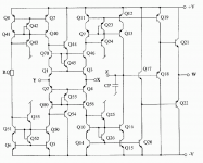
Here is a more complete schematic of the AD844 maybe someone could give that a go, with and without stacking. And notice there is already a TZ cap, wonder what value it is.
Cheers George
AD 844 - current conveyor - CFOPA
Attachments
Last edited:
Just an opinion... If you have OPA627's in your parts bin then go with that. The OPA1641 has another level of detail and transparency. So if you have to buy something then that would be my op amp of choice. AD844's are good in a stack. I have actually moved on to Pedja's DDNF circuit. It has far more current in the mirrors and to my ears is capable of better performance if buffered. Again just an opinion. I have nothing against the AD844's. It is by most accounts current starved. YMMV...
Assuming I've not blundered in designing the dac pcb layout, I'll do some listening tests with just the transformers for a week or two.
Then I will try the 844s, maybe using the built in buffer driving the transformers and then with a pair of 627s configured as differential amps as I have them in my parts bin.
Pedja's DDNF might well be preferable - only one way to find out. Will it drive the transformers I wonder?
AD844's
George, Has the designer of the chip ever commented on the current limitations on the die? Just curious. I suspect that the current is so limited to keep the die temperatures down. The discrete circuit schematic looks interesting. I hope someone makes the build attempt. Not something I can take on at this time. Not with surgery in 3 weeks and being on a walker again after that for another 4-5 weeks. Man I hate surgery....
George, Has the designer of the chip ever commented on the current limitations on the die? Just curious. I suspect that the current is so limited to keep the die temperatures down. The discrete circuit schematic looks interesting. I hope someone makes the build attempt. Not something I can take on at this time. Not with surgery in 3 weeks and being on a walker again after that for another 4-5 weeks. Man I hate surgery....
Transformers...
I run a buffer on my DDNF boards and that drives 600 Ohm line transformers (Lundahl LL1690's). The transformer operates as the reconstruction filter. If you selected a higher input impedance transformer you likely could drive the transformer directly from the DDNF board. Without a filter my ribbon tweeters indicated to much high frequency rubbish getting through.
Assuming I've not blundered in designing the dac pcb layout, I'll do some listening tests with just the transformers for a week or two.
Then I will try the 844s, maybe using the built in buffer driving the transformers and then with a pair of 627s configured as differential amps as I have them in my parts bin.
Pedja's DDNF might well be preferable - only one way to find out. Will it drive the transformers I wonder?
I run a buffer on my DDNF boards and that drives 600 Ohm line transformers (Lundahl LL1690's). The transformer operates as the reconstruction filter. If you selected a higher input impedance transformer you likely could drive the transformer directly from the DDNF board. Without a filter my ribbon tweeters indicated to much high frequency rubbish getting through.
George, Has the designer of the chip ever commented on the current limitations on the die? Just curious. I suspect that the current is so limited to keep the die temperatures down. The discrete circuit schematic looks interesting. I hope someone makes the build attempt. Not something I can take on at this time. Not with surgery in 3 weeks and being on a walker again after that for another 4-5 weeks. Man I hate surgery....
No he didn't, but then he never intended for it to be used the way we are with no NBF and the signal taken from TZ.
The more complete circuit will be interesting if someone sim's it, I got lost using that program, no patients.
Cheers George
However from comments on this thread, it worries me that there appear to be audible differences between them and I do not want to get bogged down swapping opamps for ever.
If there is no audible difference between different components, then there is no point to get into DIY. Every DIYer I know keep tweaking his gears for better sound (at least what he believe to be better). Opamp is only one small piece in the chain. If he has once found the ultimate opamp he would look to change/upgrade other parts. This is the fun part about DIY.
If you just want good sound and be done with that. It may be better to buy decent manufatured equipment. If you take into account the cost of time you spend on making a good diy gear, it may be more expensive than buying good manufactured equipment.
However from comments on this thread, it worries me that there appear to be audible differences between them and I do not want to get bogged down swapping opamps for ever.
If you really want to get away from swapping opamps then you'll be wanting a classA stage, preferably single-ended. Just as that's the end of the road for amps, so it is for I/V stages. Using opamps with their classAB output stages is pretty much always guaranteed to introduce some kind of colouration due to their generation of power supply noise.
did you read post 2001
Is there a small discrete good SQ class A circuit that you can
recommend Abraxalito ? Right now Im using Buf 03 but am looking
for a circuit which has alittle gain to go with it.
Thks
If there is no audible difference between different components, then there is no point to get into DIY. Every DIYer I know keep tweaking his gears for better sound (at least what he believe to be better). Opamp is only one small piece in the chain. If he has once found the ultimate opamp he would look to change/upgrade other parts. This is the fun part about DIY.
If you just want good sound and be done with that. It may be better to buy decent manufatured equipment. If you take into account the cost of time you spend on making a good diy gear, it may be more expensive than buying good manufactured equipment.
I agree that diy is the fun part and I have made most of my hifi and some the speakers over the last 40years. I was just getting the impression that some spend their time (I accept that it's theirs to spend) not actually listening to music but to differences between opamps.
I have been using the Sowter I/V transformers for a few years direct from the 1541's output (acrosss 47 or 100r resistor) to good effect and will find out next week whether a pair of them, differentially connected and in simultaneous mode really does sound better than a single dac.
My diy dac pcb has no digital signal processing on board - the dacs' digital inputs are taken from close to the dacs to the I2S to pcm board.
There is no onboard dem reclocking (470pf on pin 16/17 and both pin 16s linked) but a 3pin header is fitted next to the pins for external reclocking.
As for buying commercial designs - cannot afford the cost of buying something comparable and what is, to the 1541?
Hi batteryman
My point is if you are not changing the opamp then you may be changing something else. It's like you want to change from the transformer to abother output stage.
The TDA1541 is very good and my primary digital front end is a tda1541 dac with ad844 i/v and discrete fet buffer (I don't use opamp for the buffer but I believe they can sound good too).
I used to have a dual tda1541dac with passive i/v with 33 ohm resistor and then a tube gain stage. But I decided to pull out one dac and replace the passive i/v and tube with ad844 and fet buffer and found better sound. I am also aware of the limitation of the tda1541. It has its own color but very nice.
Pedja Rogic, who designed the ad844 i/v sell commercial dacs with tda1541 which has been further advanced I think. My friend has just bought a studer a730 with tda1541 dac chip (it quite expensive for an old player and it has a few NE5532 inside which many think as out of date. But I don't suspect that it sound good too)
I am trying to find a suitable opamp for my other dac with AK4396 chip
Last edited:
Parallel TDA1541A S1 Crown DAC
It has taken me about 2 years to get the sound quality out of my TDA1541A's that I was looking for. My parallel dac's see the output of a NPC SM5814 digital filter driven by a WM8804 input receiver. The dac's each have a Red Baron board. I sum the output currents into a Rhopoint I/V resistor. This feeds a tube in SRPP with a JFET. This single ended approach turned out to be the best in SQ tests. Why is it so hard to get out standing quality from the 1541? I have been asking that for a long time. It is still worth it in the long run. To date I have tried about 4 different I/V output variations.
It has taken me about 2 years to get the sound quality out of my TDA1541A's that I was looking for. My parallel dac's see the output of a NPC SM5814 digital filter driven by a WM8804 input receiver. The dac's each have a Red Baron board. I sum the output currents into a Rhopoint I/V resistor. This feeds a tube in SRPP with a JFET. This single ended approach turned out to be the best in SQ tests. Why is it so hard to get out standing quality from the 1541? I have been asking that for a long time. It is still worth it in the long run. To date I have tried about 4 different I/V output variations.
It has taken me about 2 years to get the sound quality out of my TDA1541A's that I was looking for.
Have you tried IanCanada's I2S FIFO? If not, this could be a huge improvement over traditional digital receiver/filter. IMHO, it's a game changer in audio diy world.
- Home
- Source & Line
- Digital Line Level
- Using the AD844 as an I/V