Glad you figured out the choke, because I can't find my schematic. I was about to draw up a new one.
The "gyrator" circuit will work to drop voltage ( but somehow I think a choke works better). This is slightly different than the circuit that I tried but it should work. This circuit is completely self contained with only two connections, so there is no reason you can't use it as is. Just make sure the circuit is completely isolated. P channel fets that handle high voltage are hard to find and easy to kill. It is possible to build this circuit using a tube, but again I can't find the schematic. I remember that it looked weird because the plate goes to ground.
If you put any mosfets in your power supply, add an "inrush current limiter" in series with the power line. This will help keep the initial current surge that charges the caps from blowing the fet. It is a good idea on any tube amp. They are available at DigiKey, I used the GE ones.
tubelab.com said:Glad you figured out the choke, because I can't find my schematic. I was about to draw up a new one.
The "gyrator" circuit will work to drop voltage ( but somehow I think a choke works better). This is slightly different than the circuit that I tried but it should work. This circuit is completely self contained with only two connections, so there is no reason you can't use it as is. Just make sure the circuit is completely isolated. P channel fets that handle high voltage are hard to find and easy to kill. It is possible to build this circuit using a tube, but again I can't find the schematic. I remember that it looked weird because the plate goes to ground.
If you put any mosfets in your power supply, add an "inrush current limiter" in series with the power line. This will help keep the initial current surge that charges the caps from blowing the fet. It is a good idea on any tube amp. They are available at DigiKey, I used the GE ones.
a choke is also an input current limiter, V/L = di/dt
aletheian said:
I bought tht toroid for another project that never got finished, and I figured that i could use it for this if I applied a few 'band-aids' to get the voltage down.

Toroid?
unwound it-it's easy
")
Yes the choke is a good current limiter, but if you replace it with a mosfet, the mosfet becomes the current limiter. Unfortunately these things fail shorted, which is not good for the output tubes.
My 300Beast (300B P-P) amp originally had a choke input power supply using a solid state bridge and a 350 volt 1 amp toroid. I got this idea that a regulated mosfet supply would have a lower output impedance and better sound. Well it did sound good, but every once in a while the fet would blow on power up. The Sovtek 300B's will not run on 435 volts despite what their specs show. They will run away and glow red even with -100 volts on the grid.
That amp now has the choke back. It still sounds great. B+ with the choke is 360 volts. It has always used an inrush limiter, and the fets blew every month or two. When I investigated this, I couldn't make the fets fail, so I finally gave up.
I just breadboarded the circuit with the choke between the bridge and ground. it knocked things down nicely... from 815v to 735v. I also added a small series resistor, just after the bridge and before the first cap to knick the current a bit... didn't really work all that well, but I FEEL better with it there, and it drops the voltage another bit too. I also temporarily switched to cathode bias and pentode mode rather than ultralinear, which knocked down the B+ at the plates by about 40v, so they are sitting pretty at 550v, idle bias... not too shabby. I have the grids down at 300v or so right now.
AS it sits, the sound is a little 'squishy' and there is terrible hum from my spaghetti wiring mess and alligator clips, but the tricks worked! I'll consider mosfet regulation and grid biasing later on... right now I will just revel in the fact that I finally got to use that tranny!
PS If I knew how to unwind a tranny, I would... but it has 2 6.3v taps and sheilding wrap, so I didn't want to go there and risk ruining it.
I you need to drop more volts, you can use two thermionic TV damper diodes, together with two SS diodes, in a hybrid bridge for rectification. This has a number of benefits, including zero switching noise from the SS diodes and a delayed soft start - much better for your tubes and smoothing capacitors.
tubelab.com said:SNIP...
Well it did sound good, but every once in a while the fet would blow on power up. The Sovtek 300B's will not run on 435 volts despite what their specs show. They will run away and glow red even with -100 volts on the grid.
That amp now has the choke back. It still sounds great. B+ with the choke is 360 volts. It has always used an inrush limiter, and the fets blew every month or two. When I investigated this, I couldn't make the fets fail, so I finally gave up.
The design I showed is from H&H -- without the error amplifier and all the attendant compensation. You can put a current sense resistor and NPN transistor in the main B+ loop to pinch off the gate drive when an over-current situation is present.
ray_moth said:I you need to drop more volts, you can use two thermionic TV damper diodes, together with two SS diodes, in a hybrid bridge for rectification. This has a number of benefits, including zero switching noise from the SS diodes and a delayed soft start - much better for your tubes and smoothing capacitors.
HUH... Damper diodes to ground or to circuit? I assume to ground, but I know very little of them. Where can such beasts be found?
You can use damper diodes as part (or all) of your bridge rectifier. A damper diode is a speciallized rectifier diode that was designed for the high voltage section of a TV set. They evolved to be some pretty tough rectifiers in the later vintage tube TV's. They are commonly used in audio amps because of the high H-K voltage rating, and high PIV ratings. The current handling is marginal for high power amps.
Common type numbers are 6AX4, 6AU4, 6DE4, 6DA4 octal, 6CG3 compactron. There are countless others that I can't remember now. I don't have a tube manual at work ( I would be laughed at if I did, this is a high tech electronics plant). I believe that there is a Russian flavor that is still being made. Maybe a 6D22?
Common type numbers are 6AX4, 6AU4, 6DE4, 6DA4 octal, 6CG3 compactron. There are countless others that I can't remember now. I don't have a tube manual at work ( I would be laughed at if I did, this is a high tech electronics plant). I believe that there is a Russian flavor that is still being made. Maybe a 6D22?
tubelab.com said:You can use damper diodes as part (or all) of your bridge rectifier. A damper diode is a speciallized rectifier diode that was designed for the high voltage section of a TV set. They evolved to be some pretty tough rectifiers in the later vintage tube TV's. They are commonly used in audio amps because of the high H-K voltage rating, and high PIV ratings. The current handling is marginal for high power amps.
Common type numbers are 6AX4, 6AU4, 6DE4, 6DA4 octal, 6CG3 compactron. There are countless others that I can't remember now. I don't have a tube manual at work ( I would be laughed at if I did, this is a high tech electronics plant). I believe that there is a Russian flavor that is still being made. Maybe a 6D22?
Ahhh... tubes... I thought it was just a SS thing. I actually have some 6ax4 around... I thought it was a normal 6v rectifier! WEll there is yet another option.
I looked into this thread very late - what a whole lot of nifty ideas!
But just to remind (if necessary) that a choke input filter can produce nasty spikes every time the choke "turns off" because of stored energy. There is usually an RC across the choke - values of 10K (0.5W) and 10 nF (3 KV!) appear to be common. I have never modelled this (trusted recommendations) but the 3KV capacitor rating gives an idea of the magnitude of spikes to be expected.
But just to remind (if necessary) that a choke input filter can produce nasty spikes every time the choke "turns off" because of stored energy. There is usually an RC across the choke - values of 10K (0.5W) and 10 nF (3 KV!) appear to be common. I have never modelled this (trusted recommendations) but the 3KV capacitor rating gives an idea of the magnitude of spikes to be expected.
Hey Tubelab...
Hey Tubelab,
I got a nasty buzz after I switched to that choke in the ground leg setup. It occurred to me that I have no ides how to orient the first filter cap with that setup. I had it tied to the "power" lug on my 2 point star ground layout. Is there a better way to do it, and could that be my buzz issue?
tubelab.com said:"Choke in the ground leg"
I will post the schematic when I get home tonight
Hey Tubelab,
I got a nasty buzz after I switched to that choke in the ground leg setup. It occurred to me that I have no ides how to orient the first filter cap with that setup. I had it tied to the "power" lug on my 2 point star ground layout. Is there a better way to do it, and could that be my buzz issue?
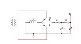
Example of chokes in ground side
Alethian,
Here is an example circuit (the Chinese "Music Angel" 845 SET). Both the main HT and the Driver HT use chokes in the ground side. Note where the earth connections and the caps go. If you put the ground connection in the wrong place you will certainly get a nasty buzz.
Hint save attachment to file and then open it full size using Windows Picture and Fax Viewer. Any missing lines will reappear.
Cheers,
Ian
Attachments
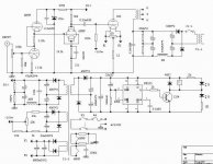
This HV power supply is the same as the one that I use on the 845SE except I use tube rectifiers.
The Buzz can be caused by grounding issues, or the buzz can be caused by the voltage transients that occur in the choke.
Remember from electronics 101 that an inductor tends to keep the flow of current constant. It does that by releasing its stored magnetic energy as current. When there is no place for that current to flow the voltage will rise abruptly often to kilovolt levels. In a pure choke input filter, there is a period of time where the diodes are reverse biased, so there is no path for current flow. The inductor voltage rises to the point that the diodes break down. This fast discharge of energy will cause a raspy buz in the amp. It will also cause blown diodes.
OK, now how do I fix it? Try a small cap across the bridge rectifier, like a cap input filter. 1 uF . Try a resistor across the choke something like 5K 5W. I have heard mention of snubber networks across the choke, but I haven't tried them. The problem is less obvious with tube rectifiers.
Your circuit is correct.
depends upon Cjo of the diode and L(leakage) of the transformer.aletheian said:Sweet.
Would you recommend bypassing all the bridge diodes with capc or resistors, or just one from AC to AC, or B+ to ground (well, to choke more like)?
Thanx for all the help.
- Status
- This old topic is closed. If you want to reopen this topic, contact a moderator using the "Report Post" button.
- Home
- Amplifiers
- Tubes / Valves
- Using a mosfet to drop B+?