Ok, some new measurements including port response.
The first is the port response FR (includes distortion),
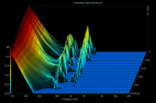
second is the CSD at the port,
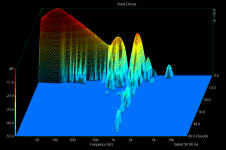
third is the Burst Decay at the port,
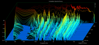
and the last is just a new full range CSD with no octave smoothing, wider gate and more db levels.
I think this speaker has serious internal reflection issues. I don’t think its panel resonance issues as much but more of internal reflections.
The first is the port response FR (includes distortion),
second is the CSD at the port,
third is the Burst Decay at the port,
and the last is just a new full range CSD with no octave smoothing, wider gate and more db levels.
I think this speaker has serious internal reflection issues. I don’t think its panel resonance issues as much but more of internal reflections.
Attachments
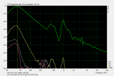
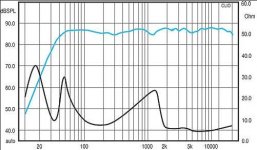
Your first measurement is a classic port response, you see the peak at the box tuned frequency around 40Hz, tapering off from there up to 300Hz, then various spurious resonances.Ok, some new measurements including port response.
The first is the port response FR (includes distortion),
second is the CSD at the port,
third is the Burst Decay at the port,
The one at 1Khz is most likely the pipe mode resonance that occurs at the frequency where the pipe/tube is a half wavelength long. (about 17.2cm) As you can see this resonance is very strong, only 20dB down below the bass resonance, (14dB in the far field once baffe step loss has occurred) which is pretty typical for a pipe resonance in a port, and a good reason why I prefer ports on the back...
The resonance at 400Hz could be an air space standing wave resonance in the box which is being emitted via the port. Look for internal box dimensions (length/width/height) that are about 43cm long. (If theres no dimension that's that big it could be a room artefact depending on how you've done the measurement)
Unfortunately this last measurement is still no good - you've gone the wrong way and used an even longer gate time of 23ms. 23ms is enough time for sound to travel 23 feet so you will have 23 feet worth of room reflections included in your measurement.and the last is just a new full range CSD with no octave smoothing, wider gate and more db levels.

This clearly shows up in the multiple slow decaying long ridges between 300Hz and 6Khz - what you are measuring is the decay of the sound field in the room, not the decay of any resonances in the driver or speaker itself, which will be over and done with in less than 4ms.
I can't stress enough how critical it is to exclude reflections when generating a CSD, because the way a CSD works is by sliding a finite length window across the impulse - so anything that is present near the end of the impulse window will also show up at every time before that as well - so a reflection arriving near the end of the initial window period will be present at ALL times (in the z axis on the graph) which is why you see these long ridges that hardly drop off.
As I said in my previous message, 5.6ms is the longest possible gate time you can hope to use in a room with a 2.4 metre ceiling, speaker at half the ceiling height, and microphone at 50cm. If the microphone is further away or the speaker is closer to a boundary then it will be even shorter than this.
If you're unsure about where to set the end marker, post an image of the first 6ms worth of the impulse response with the amplitude turned up so that the initial impulse is at least full screen, and I can give you an idea of where to set the end marker. (Another possibility is if you have the registered version of ARTA you could send me the original PIR file to look at and I can generate a CSD from it and find what gate time etc to use for the most meaningful result)
As mentioned above, 1Khz will be a pipe resonance, and 400Hz is most likely an internal air space resonance caused by internal standing waves, both of which you'll easily measure right at the opening of the port.I think this speaker has serious internal reflection issues. I don’t think its panel resonance issues as much but more of internal reflections.
Finding panel resonances generally requires use of an accelerometer attached to the panels instead of a microphone, as the sound emitted by the panel will tend to be swamped by the direct sound from the driver and the port opening...
Last edited:
About the measurements -
The mic is placed quite close (~0.5m) to the speaker and both are ~1m above a carpet+rug floor. The next nearest surface (wall) would be atleast 2m away. And I used moderate volume (lower volume=less reflections) and I couldn’t see anything that would look like a substantial reflection of the pulse so I just opened the gate wide up to get good points resolution. I tweaked the db scale to get a balance between too much and too little detail on the chart. I just have the free version of ARTA but I will post a sreen shot of the pulse.
About the dimensions -
Port length (as per manual, I have not measured) is 6¼” (~16cm). It’s a 2” dual flared rear facing port and its placed away from the woofer, meaning the woofer is in the lower half of the baffle and the port is on the upper half of the back.
And its ¾” mdf construction so the longest side internally would be about 15.5” (39-40cm)
Are there any ways to reduce secondary port resonances ?
It doesn't matter how far away the further walls are, its the closest boundary to either the speaker or microphone that matters, and limits the maximum gate time you can use.About the measurements -
The mic is placed quite close (~0.5m) to the speaker and both are ~1m above a carpet+rug floor. The next nearest surface (wall) would be atleast 2m away.
If the speaker is only 1m from the floor that's your closest boundary (and presumably the microphone is the same height from the floor as well) so with a 50cm microphone distance your first reflection is going to arrive at 4.54ms. (Courtesy of the floor bounce calculator page I linked to earlier)
So what you would do is set the start marker to the exact start of the impulse, adjust the end marker until it says the gate time is a bit less than this, say 4.3ms, then finally move the start marker slightly earlier by about 0.2ms to make sure that it isn't truncating the beginning of the impulse. Take a CSD using this (and adjust the CSD parameters to give a total time scale on the Z axis of about 4ms) and you'll see a big difference in the results.
Doesn't work that way unfortunately. The reflections go up and down in unison with the volume level.And I used moderate volume (lower volume=less reflections)
If they didn't, the room would somehow be non-linear, which it isn't.In fact if you try to perform a CSD measurement at a low volume level you'll run into a lot of trouble with background noise - for example if your PC has a fan and/or noisy hard drives the noise will show up in the measurements and look quite similar to the ridges that you see on that measurement, depending on the noise spectrum the PC is putting out...
To minimise this I do CSD's at a relatively high volume level - around 90-95dB SPL at 1 metre, and even then I can only get about 30dB dynamic range at most due to the noise of the PC in the same room...(ideally I would put the PC in another room with the door shut but its not practical for me)
If you've got carpet on the floor it will absorb a lot of high frequencies so the reflected impulse will have its sharp edge removed making it hard to identify where it is by looking at the impulse response...sometimes its better to not bother with carpet if you're going to do a gated measurement so you can reliably identify where the first reflection begins in time and eliminate it.and I couldn’t see anything that would look like a substantial reflection of the pulse so I just opened the gate wide up to get good points resolution.
Either that or just calculate the maximum allowable gate time based on the the measurement geometry as above. Just because you can't visually see the reflections in the impulse doesn't mean they aren't there and tainting your CSD results - we're trying to get results down to 30dB below the main impulse and theres no way you would see a reflection 30dB down visually in the impulse window, at least not without a lot of zooming in.
Opening up the gate time wide simply lets all the room reflections in and destroys the results. No free lunch here unfortunately. Doing measurements of these types in typical rooms is challenging and right near the edge of what is possible due to the limited reflection free window available.
If your measurement is full of room reflections or ambient noise from your PC then we don't really know whats going on. The best amplitude range to use will be a bit more clear once the measurement settings like gate time are correct. Typical ambient noise generally limits you to a maximum range of about 30dB before you are just seeing the ambient noise floor in the measurement, while anything less than 20dB isn't very informative as it cuts off a lot of important information. (We can hear resonances more than 20dB down, the threshold where we no longer hear them is more like 30dB down)I tweaked the db scale to get a balance between too much and too little detail on the chart. I just have the free version of ARTA but I will post a sreen shot of the pulse.
Ok so the 1Khz peak is a pipe mode resonance then, as it matches the length very closely. If the port is on the back you don't have much to worry about as the baffle formed by the cabinet means that very little if any of that 1Khz resonance will reach the listener, even if its not far from a wall.About the dimensions -
Port length (as per manual, I have not measured) is 6¼” (~16cm). It’s a 2” dual flared rear facing port and its placed away from the woofer, meaning the woofer is in the lower half of the baffle and the port is on the upper half of the back.
And the longest internal side matches the 400Hz resonance fairly well. That one is probably far more audible than the 1Khz one both because the lower frequency is more omnidirectional and may wrap around the cabinet, and also because you'll probably get some leakage of this resonance through the cone of the woofer itself.And its ¾” mdf construction so the longest side internally would be about 15.5” (39-40cm)
For the pipe mode resonance at 1Khz I wouldn't worry about it if the port is on the back, but the standing wave resonance in the main cabinet at 400Hz may need some attention.Are there any ways to reduce secondary port resonances ?
The problem is the only way to really eliminate standing wave resonances in a cabinet is adding stuffing in the middle, damping layers on the walls will help a bit but only do so much as the particle velocity is low at the walls and high near the middle. In a closed box this is easy but with a vented box too much stuffing will lower the Q of the box/port resonance (especially if the path from the woofer to the port is obscured) and reduce the bass output a lot, so stuffing of a bass reflex box is a bit of a delicate balancing act.
I've never really had much luck with stuffing of bass reflex cabinets, (I tend to just line the walls with wool based carpet under-felt and call it a day) but perhaps others have some suggestions. Expect to lose some bass though.
Last edited:
Are there any ways to reduce secondary port resonances ?
If you can lower the level of the ~1kHz sound in the enclosure at the inner entrance to the port, it will reduce the resonance mode. You can do this with better internal damping, as suggested already. Also, if you can eliminate a direct line of sight path from the woofer to the port entrance, it will help. You could either add a brace in between, or strategically place the damping material.
The fact that it's a rear port helps, but I've had port resonance modes like that and even on a rear ported setup, I noticed a sloppy ported midrange sound at the listening position.
I have always felt that the low-mid voice/speech range sounded a little bit boxy/honky,
Not sure if this was already discussed, but is the rear of the driver cutout chamfered?
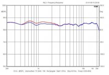
percy, I just had a look at notching out the 850Hz resonance in this frequency plot from parts express.
It can be done, but you then end up with issues higher up the range around 2kHz. That really calls for a complete redesign.
The actual enclosure can be criticised for its poor ratio of dimensions which explain the 400 and 800Hz peaks to some extent. But really you are complaining that a boxy reflex sounds, er, boxy. I think that is the nature of the beast. You can't fix that.
An externally hosted image should be here but it was not working when we last tested it.
It can be done, but you then end up with issues higher up the range around 2kHz. That really calls for a complete redesign.
The actual enclosure can be criticised for its poor ratio of dimensions which explain the 400 and 800Hz peaks to some extent. But really you are complaining that a boxy reflex sounds, er, boxy. I think that is the nature of the beast. You can't fix that.
But really you are complaining that a boxy reflex sounds, er, boxy. I think that is the nature of the beast. You can't fix that.
Sure you can fix it. There is a compromise to be made with any reflex enclosure. When you add more damping, reflex response is attenuated. There is an optimal point (which may be user dependent, based upon preference) where sufficient damping eliminates the 'boxy' reflex sound while port response is still adequate. In addition, the port can be shortened to compensate for the reduced resonant effect (and larger apparent volume) due the damping. This will raise F3/F10 slightly which is part of the tradeoff. A tool such as Unibox is very useful to use to see the effects of the damping, port length, tuning frequency, etc. Using this tool combined with impedance measurements of the box, a nice compromise can usually be made.
Sure you can fix it. There is a compromise to be made with any reflex enclosure. When you add more damping, reflex response is attenuated. There is an optimal point (which may be user dependent, based upon preference) where sufficient damping eliminates the 'boxy' reflex sound while port response is still adequate. In addition, the port can be shortened to compensate for the reduced resonant effect (and larger apparent volume) due the damping. This will raise F3/F10 slightly which is part of the tradeoff. A tool such as Unibox is very useful to use to see the effects of the damping, port length, tuning frequency, etc. Using this tool combined with impedance measurements of the box, a nice compromise can usually be made.
Usher 8945A 7" carbon fibre woofer:
Specifications: • Power handling: 80 watts RMS/90 watts max • VCdia: 1-5/8" • Le: 0.46 mH • Impedance: 8 ohms • Re: 5.8 ohms • Frequency range: 35-8,000 Hz • Fs: 35 Hz • SPL: 87 dB 2.83V/1m • Vas: 1.21 cu. ft. • Qms: 1.96 • Qes: 0.37 • Qts: 0.31 • Xmax: 6.0 mm • Dimensions: Overall diameter: 7", Cutout diameter: 6-1/4", Depth: 3-1/16".
OK, I follow that. Shorten the reflex tube and fill the 0.75 cubic foot cabinet with stuffing. This will damp down the response and the peaks with it. Moving more towards aperiodic damped port or closed box and a different bass sound. You could attenuate the tweeter slightly more too. Sounds like a plan.
Oh, I've just had a brilliant idea! I amaze myself sometimes...
Some people ask what Jesus would have done in this situation. Me, I ask myself what TROELS would do!
Here's the answer. Apply a SHALLOW electrical notch to the input of the woofer at about 1kHz. 4.7mH, 10uF and about 20 ohms should do. I got the idea from Troels SEAS TOK loudspeaker.
SEAS TOK
Here's the wretched "In your face" Usher 701 speaker below, and here's Troels' correction. About right, isn't it? Might add a couple of dB attenuation to the tweeter to line it up right.
Attachments
- Status
- This old topic is closed. If you want to reopen this topic, contact a moderator using the "Report Post" button.
- Home
- Loudspeakers
- Multi-Way
- Usher 701 resonance issues ?