*Cough* that's me 
Thread:
http://www.diyaudio.com/forums/tubes-valves/110155-blasphemy-im-sure.html
Web link:
Compound Tube Contest (same as linked above, thanks Miles)
Page includes scope shots, so you can see the oscillator is a little "humpy", since it's just an RC oscillator, but it's not too bad, because it's low amplitude, so the resistor approximates a current source.
I have the recorded waveform laying around somewhere if you'd like to compare distortion. As long as you stay out of clipping, the distortion is astonishingly small. I'm not entirely sure why this turned out; small differences in parasitic capacitances could easily screw it up. But that it did is very interesting.
One side effect of class D: because the square wave is only ever driving a beam pentode (Ron ~ 100 ohms) or a diode (about 50 ohms), the output impedance is really, really low. Despite the crummy OPT, this thing did single digit hertz without even thinking. The OPT itself will fart away from saturation, but the amp itself is true DC coupled.
With a proper push-pull output stage, efficiency can be way higher (no class D-A network necessary!). Imagine getting 200W from a pair of 31LQ6. Without breaking a sweat.
Tim
Last edited:
I thought so, the waveform looks ungodly nonlinear in those pictures
Ah, but read the description:
I'm pretty sure the leading edge "nubs" are artifacts of my scope -- this unusually short (6 div tall), unusually green shot is of the Heathkit, which has, shall we say, primitive triggering circuitry.
The waveform is indeed a smooth, sloped triangle as measured with the Tek. I just didn't take a picture of it. More proof that it's a trigger artifact:
http://webpages.charter.net/dawill/tmoranwms/Elec_Compound3.jpg
The rising edges have sideways *nubs*. That's not even a graph of a function, it's going sideways. Yes, the trigger circuit is awful...
The transfer functions and other waveforms on the page show the excellent results of this waveform.
Tim
It is always interesting to see different approaches to same problem. It was that webpage that sparked my interest some time ago, I hope to actually have it implemented at some point. Hobby projects are on sidelines at the moment so I settle for "make sur it works in principle without delving into already proven bits, push away, start on something new", a bit like evidence in mathematics
Bringing out this old thread with the same concerns...
I have bunch of these common cathode Triode Pentodes tubes like the 6X8, 6HB7 and 6LJ8...has anybody worked or knowledge on uses of this tube aside from those perviously discussed above...
Any inputs are greatly appreciated...
I have bunch of these common cathode Triode Pentodes tubes like the 6X8, 6HB7 and 6LJ8...has anybody worked or knowledge on uses of this tube aside from those perviously discussed above...
Any inputs are greatly appreciated...
Bringing out this old thread with the same concerns...
I have bunch of these common cathode Triode Pentodes tubes like the 6X8, 6HB7 and 6LJ8...has anybody worked or knowledge on uses of this tube aside from those perviously discussed above...
Any inputs are greatly appreciated...
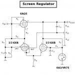
6X8's are very useful as voltage regulator error amps. (Attached). This way, the VR just draws its own current. You can include an RC noise filter since you're not connecting a capacitor across the VR tube (makes an oscillator).
The pentode is also a high gain device, and that's always good for any voltage regulator. Most people don't like 'em and so they aren't pricey.
Attachments
Thanks Miles for the info...do you have the values to play with?...i have a more than a dozen NOS of this tube and any other use will be better.
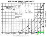
Design example attached. If you have 'em, might as well use 'em. The pentode half of the 6X8 is quite a linear small signal pentode. You can always use 'em for low level amplification as an unbalanced differential with the triode half being the input. It might save you a few pF in device capacitance.
You could also use 'em to implement a kind of paraphase splitter.
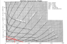
Another possibility is trioding the pentode half to get a dual triode. Pentoded, the pent half is very similar to the triode half.
You could also use 'em as intended: a high frequency mixer/oscillator.
(Now the price of these are likely to go up.
)Attachments
Thanks again for the tip... Might try both option as unbalanced diff'l input and strapped the pentode to triode.Design example attached. If you have 'em, might as well use 'em. The pentode half of the 6X8 is quite a linear small signal pentode. You can always use 'em for low level amplification as an unbalanced differential with the triode half being the input. It might save you a few pF in device capacitance.
You could also use 'em to implement a kind of paraphase splitter.
Another possibility is trioding the pentode half to get a dual triode. Pentoded, the pent half is very similar to the triode half.
You could also use 'em as intended: a high frequency mixer/oscillator.
(Now the price of these are likely to go up.
@ AJT...thanks also for the links you had given me...now I know that the tube I got are not totally useless...
- Status
- This old topic is closed. If you want to reopen this topic, contact a moderator using the "Report Post" button.
- Home
- Amplifiers
- Tubes / Valves
- Usefulness of 6X8 tube?