Hi Paul, hopefully you are still around over there, about to go to bed here, so with any luck you may have replied by the time I get up!
Very easy to do more indoor measurements, will do both .5 and 1m measurements, certainly a lot easier to do them whilst it's all set up in here before the hassle of taking them outdoors.
However, to be honest, I don't really understand the method or theory of ground plane measurements. Do you have a quick link? My thoughts on measuring outdoors is that by eliminating room reflections we can have a longer gate and more closely simulate anechoic measurements, within reason. Is ground plane measurements any different?
Yes, with the deqx we simply get as long a measurement window as possible by cutting off the measurement just before the first reflection, again an advantage of going outdoors. If I measure outdoors, I am able to position them in such a way that the ground is a good 1.5 m away from the speaker, ie the box can be raised on a platform of kinds. However, whilst this seems to me to be the obvious way to do it, it seems to conflict with your statement of using the ground to simulate the floor....what do I not understand??
Is the use of the ground (floor) a necessary peculiarity of dipoles?
Ok, won't give up just yet, at least we are all still learning ha ha. If done outdoors, I will do perhaps a series of measurements of increasing distances, that may help us to pick up trends.
The irony of all this is that if them PHL drivers won't do the range I'm after, I of course could use the peerless drivers I was going to use in the sub as the dipoles themselves, indeed that has been shown to work in the orions. However, if I used the peerless as dipoles I am unable to use these PHL's as a sub under the peerless as they don't go low enough! Some sort of Murphys Law I suppose.
Thanks Rudolf for the link, will chase a little further and see where we end up...keep your fingers crossed for me")
Very easy to do more indoor measurements, will do both .5 and 1m measurements, certainly a lot easier to do them whilst it's all set up in here before the hassle of taking them outdoors.
However, to be honest, I don't really understand the method or theory of ground plane measurements. Do you have a quick link? My thoughts on measuring outdoors is that by eliminating room reflections we can have a longer gate and more closely simulate anechoic measurements, within reason. Is ground plane measurements any different?
Yes, with the deqx we simply get as long a measurement window as possible by cutting off the measurement just before the first reflection, again an advantage of going outdoors. If I measure outdoors, I am able to position them in such a way that the ground is a good 1.5 m away from the speaker, ie the box can be raised on a platform of kinds. However, whilst this seems to me to be the obvious way to do it, it seems to conflict with your statement of using the ground to simulate the floor....what do I not understand??
Is the use of the ground (floor) a necessary peculiarity of dipoles?
Ok, won't give up just yet, at least we are all still learning ha ha. If done outdoors, I will do perhaps a series of measurements of increasing distances, that may help us to pick up trends.
The irony of all this is that if them PHL drivers won't do the range I'm after, I of course could use the peerless drivers I was going to use in the sub as the dipoles themselves, indeed that has been shown to work in the orions. However, if I used the peerless as dipoles I am unable to use these PHL's as a sub under the peerless as they don't go low enough! Some sort of Murphys Law I suppose.
Thanks Rudolf for the link, will chase a little further and see where we end up...keep your fingers crossed for me
Member
Joined 2003
Good morning Terry!
The elevated driver/ground plane measurements are just different approaches to minimizing or eliminating reflections. I don't have any links but Google should find a good writeup or two.
Quickly, for GP, you place the microphone on the floor (preferably a large outdoor concrete pad well away from obstructions). Place the woofer/baffle as close as possible to the ground, aiming it at the microphone. The ground creates a "mirror image" of the driver...so SPL in inflated but you don't have to worry about a strong reflection only 1.5M distant. It is important to get the woofer right down at the surface so you get a mirror image rather than an ill-timed reflection. This approach works well because you can use a longer time window.
The GP method also hints at permanently mounting the woofer right down against the floor because you get a "free second driver". Less EQ boost, lower amp power, lower excursion, lower distortion, etc. You are correct that integration with the mid would be optimized with the woofer clustered but, at 300Hz, the floor position is still substantially less than a wavelength from the mid. So, another suggestion is to download a floorbounce calculator and use that as one more input to your decision.
Paul
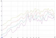
OK, quick re-do of the indoor measurements, starting at a distance of 1/2 meter, then 1, 1.5 and 2 meters.
I have seperated the traces for ease of viewing, the repeating pattern of rise and fall is evident in each graph, so I assume are not related to a particular room interaction at a point, but must be some sort of baffle interaction?
Have no large concrete area for the ground plane measurement, but I can put it on an ungrassed area which is pretty hard packed and hopefully will simulate the concrete reasonably closely.
Attachments
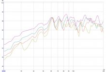
Again, as I am too dumb to post multiple picture I have another post! As I won't be able to do anything outside for the next few days, just to see what happened I added wings to the baffle. These wings are the same height (1.2 m) and each are 600mm long, added to the existing baffle of 1.2 m. One each side .
The response as expected is better, but of course in practical terms the whole thing is getting huge, so unlikely to everbe a goer.
At the end of the day we are not really learning anything new here, as all these differences are probably well predicted by existing theory.
Whilst reserving final decisions till outside measurements, and although others may be more hopeful about this than I am at the moment ha ha,if we were to assume these drivers are not feasible for what i would like, by reference to the parameters I posted earlier, which one (or more) of those parameters would be the one to see and say "naaaah, that driver won;t work in this arrangement" ? Just so I at least walk away with a bit of analytical understanding of it all.
Thanks to all who have taken an interest, will do some outside measurements in the next few days. Any last minute suggestions on those measurements, or indeed any observations/conclusions on the measurements so far, are warmly received.
Attachments
Paul,
I have some pro drivers that a friend measured as having break up peaks at about only 2* my hoped for Xo Hz:
Can you explain why the harmonics, which pass through the XO with al, the driver signal, would not also be attenuated by the crossover?
And also why:
What is the distinction between acoustic response and frequency response generally?
Thanks,
Rick
I have some pro drivers that a friend measured as having break up peaks at about only 2* my hoped for Xo Hz:
Harmonic distortion components generated within the driver are not attenuated by the crossover
Can you explain why the harmonics, which pass through the XO with al, the driver signal, would not also be attenuated by the crossover?
And also why:
the notch filter I mentioned for a "3x crossover" won't help the driver harmonic situation either...the purpose of the notch is to keep acoustic response on target.
What is the distinction between acoustic response and frequency response generally?
Thanks,
Rick
Member
Joined 2003
The key is "generated within the driver ". Harmonics generated in the amplifier of course pass through the XO and are attenuated along with the rest of the signal. Harmonics generated by the driver itself do not pass through the XO and are not attenuated. This is important because driver distortion is usually higher than amp distortion or anything else further back in the chain.Can you explain why the harmonics, which pass through the XO with al, the driver signal, would not also be attenuated by the crossover?
I was referring to acoustic frequency response. You may be thinking about acoustic vs electrical response. Our objective is an acoustic output...which is the combined response of the XO + driver. Acoustic output will spike if a driver breakup spike is combined with a smooth XO electrical rolloff. So, driver breakup peaks are usually offset by an XO notch.What is the distinction between acoustic response and frequency response generally?
Bottom line is to manage breakup with attention to driver harmonics and any appropriate XO compensation.
- Status
- This old topic is closed. If you want to reopen this topic, contact a moderator using the "Report Post" button.