This is an idea I have been playing around with for a while, and I can't seem to find anywhere that this has been discussed.
So to set up an example: A sealed enclosure rolls off at 12 db/octave, and lets say the F3 is 70 hertz. Room gain is being ignored for the sake of discussing theory here. Let's also say that it is a 2 way speaker, with a full range driver and woofer. Xover is 400 hz or somewhere around there. The full range driver has an SPL of 90 db/w at 1 meter. There are actually 4 woofers, 4 ohm impedance each, set up in series/parallel so that the overall SPL is 105 db/w and the impedance of all four woofers wired together is still 4 ohms.
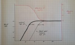
Now, heres the plan: after the Xover, a second low pass filter was added in series with the woofers with a roll-off of 12 db/octave, with the frequency chosen so that the slope of the roll off matches the roll off of the enclosure. In parallel with the LP filter there is a resistor to provide 15 db of attenuation.(similar in principal to a BSC circuit) This means at frequencies above the 70 hz F3 of the sealed enclosure, the full range driver and woofer both have an SPL of 90 db/w. As the frequency goes lower, the roll off of the sealed enclosure is matched (and counteracted by) the roll off of the LP filter/resistor circuit, effectively making the overall response flat for another octave, before the 12 db/octave roll off of the sealed enclosure takes over again.
It is pretty much a BSC circuit being re-purposed.
While I think this might work, I can foresee there being some problems with the theory. Any feedback?
So to set up an example: A sealed enclosure rolls off at 12 db/octave, and lets say the F3 is 70 hertz. Room gain is being ignored for the sake of discussing theory here. Let's also say that it is a 2 way speaker, with a full range driver and woofer. Xover is 400 hz or somewhere around there. The full range driver has an SPL of 90 db/w at 1 meter. There are actually 4 woofers, 4 ohm impedance each, set up in series/parallel so that the overall SPL is 105 db/w and the impedance of all four woofers wired together is still 4 ohms.
Now, heres the plan: after the Xover, a second low pass filter was added in series with the woofers with a roll-off of 12 db/octave, with the frequency chosen so that the slope of the roll off matches the roll off of the enclosure. In parallel with the LP filter there is a resistor to provide 15 db of attenuation.(similar in principal to a BSC circuit) This means at frequencies above the 70 hz F3 of the sealed enclosure, the full range driver and woofer both have an SPL of 90 db/w. As the frequency goes lower, the roll off of the sealed enclosure is matched (and counteracted by) the roll off of the LP filter/resistor circuit, effectively making the overall response flat for another octave, before the 12 db/octave roll off of the sealed enclosure takes over again.
It is pretty much a BSC circuit being re-purposed.
While I think this might work, I can foresee there being some problems with the theory. Any feedback?
Draw a schematic please.  From what I can tell adding a resistor to this circuit is doing nothing but wasting power. Each woofer would have to be 99dB/w and would be better if driven at a lower power level than to waste that 15dB of power (MASSIVE). The 2nd order network corresponding to the Fb of a sealed box would result in a 24dB acoustic slope reducing the output at low frequencies, not extending them.
None of this makes any sense as is, other than a lot of power/amp headroom being wasted away as heat. Kinda like driving around town with the emergency brake always on.
From what I can tell adding a resistor to this circuit is doing nothing but wasting power. Each woofer would have to be 99dB/w and would be better if driven at a lower power level than to waste that 15dB of power (MASSIVE). The 2nd order network corresponding to the Fb of a sealed box would result in a 24dB acoustic slope reducing the output at low frequencies, not extending them.None of this makes any sense as is, other than a lot of power/amp headroom being wasted away as heat. Kinda like driving around town with the emergency brake always on.
Greebster,
You are misunderstanding me, which is understandable.
Think of it more generally and ignore the whole description of the circuit, which is admittedly confusing:
The woofers have a combined efficiency higher than that of the full range. At frequencies above the roll off of the sealed enclosure, the woofers are attenuated to match the full range. This attenuation decreases as the box tuning rolls off at the same rate as the box tuning roles off, effectively canceling out the roll off until there is 0db of attenuation on the woofers. At that point the roll off of the enclosure tuning will come into play as normal.
I will add some diagrams and schematics tomorrow- I just don't think my original post describes the theory generally enough.
Dumbledog:
What you are proposing seems perfectly plausible, although - as you have already anticipated - it will cost you a substantial amount of amplifier power. The other catch is that low-pass filter = series inductor, and at those frequencies the required inductance will be quite large. I have played around with notch filters in the 80 - 100 Hz. range, and the air-core inductors needed ended up being pretty big. This in turn will add resistance and further power dissipation, which can be minimized by use of heavy gauge ($$) wire. I know iron-cored inductors are generally frowned upon for crossover use, but it might be worth considering this option. Another option you might consider would be to use a filter at line level (either passive or active) before the power amplifier stage to achieve your goal. I believe that is the method commonly employed by many commercial systems and suggested by some of the classic published Thiele-Small "alignments".
What you are proposing seems perfectly plausible, although - as you have already anticipated - it will cost you a substantial amount of amplifier power. The other catch is that low-pass filter = series inductor, and at those frequencies the required inductance will be quite large. I have played around with notch filters in the 80 - 100 Hz. range, and the air-core inductors needed ended up being pretty big. This in turn will add resistance and further power dissipation, which can be minimized by use of heavy gauge ($$) wire. I know iron-cored inductors are generally frowned upon for crossover use, but it might be worth considering this option. Another option you might consider would be to use a filter at line level (either passive or active) before the power amplifier stage to achieve your goal. I believe that is the method commonly employed by many commercial systems and suggested by some of the classic published Thiele-Small "alignments".
sounds similar to the short line I built some years ago where the crossover progresssively cut off the drivers the further out I went. At the lowest frequency all drivers worked in unison but as you came closer to the tweeter in frequency in this MMTMMM down to where only one of the mids crossed to the tweeter.
Similar to adding additional subs to a system. If the primary speakers have a sub each, but with only partial BSC if any and then adding 2-4 more.
Similar to adding additional subs to a system. If the primary speakers have a sub each, but with only partial BSC if any and then adding 2-4 more.
Bump.
Someone must have thought of this or even tried it already.
They have, both passive and active. Earliest implementation that I have seen was in the seventies. You can read about active here
Linkwitz Transform Subwoofer Equaliser
Here is a passive version of the cross-over designed for the ZUS 2-way Isobaric loudspeaker. It used two Peerless HDP835025 woofers and Scanspeak D2008 tweeter. The speaker as a system has a pretty flat response down to 20 Hz but they never went into production due to the very low efficiency.
Attachments
The filter you propose is similar to what Bag End do with their ELF speakers, but they do it actively. You will find trying to do it passive that you need big inductors. Also, despite what sentivity figures say, you haven't got that much efficiency to throw away in practice.
Or even more simple, get a DSP unit. With DSP you are more likely to hit your goal response and you won't have to trade it for less SPL like in a passive crossover.
Uhm no. That's not correct.
Ahh got the OP's Q now wants to compensate for the power requirement /excursion limit of doing such with much higher efficiency drivers and by increasing surface area by 4x the norm.
Using separate subs todo the same would have the advantage of strategic placement to compensate for room modes a la Geddes multisub approach. That is unless say 2 of the 4 drivers were in their own enclosure placed elsewhere. Nothing says this cant be done and works better.
wants to compensate for the power requirement /excursion limit of doing such with much higher efficiency drivers and by increasing surface area by 4x the norm.Using separate subs todo the same would have the advantage of strategic placement to compensate for room modes a la Geddes multisub approach. That is unless say 2 of the 4 drivers were in their own enclosure placed elsewhere. Nothing says this cant be done and works better.
Thanks for the responses so far.
I am familiar with the concept of the Linkwitz Transform circuit, and have played around with the design of them for the various speakers I dream up. For both the Linkwitz and what I am proposing here, there is one disadvantage, and that is power. While a Linkwitz Transform increases bass extension through amplification of certain frequencies, this circuit here increases bass extension through selective attenuation of a high-efficiency design. However, I can't help but feel that with a LT, you are using more power than would be used here. Here, efficiency is being achieved through large cone area. In the end, the overall speaker system still has an SPL of 90 db/w, but extension for another octave below normal sealed enclosure cutoff. It is just that the woofers are more efficient (by way of the added circuit) at lower frequencies. It is wasted efficiency, as opposed to wasted power.
Now, this does mean that to achieve higher listening volumes, you would need more power than you would otherwise need without the attenuation, but the FR driver has an SPL of 90 db/w anyway, so it is the limiting factor to overall speaker efficiency.
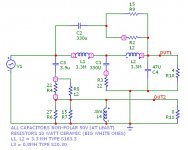
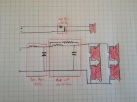
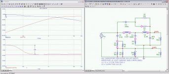
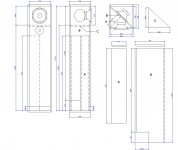
I attached some quick and dirty hand drawn graphs and schematics that I did when I got a chance. I had tried using BoxSim, but getting the program to sim 4 drivers is a little difficult. Hopefully I will get it working so we can see the results.
I am familiar with the concept of the Linkwitz Transform circuit, and have played around with the design of them for the various speakers I dream up. For both the Linkwitz and what I am proposing here, there is one disadvantage, and that is power. While a Linkwitz Transform increases bass extension through amplification of certain frequencies, this circuit here increases bass extension through selective attenuation of a high-efficiency design. However, I can't help but feel that with a LT, you are using more power than would be used here. Here, efficiency is being achieved through large cone area. In the end, the overall speaker system still has an SPL of 90 db/w, but extension for another octave below normal sealed enclosure cutoff. It is just that the woofers are more efficient (by way of the added circuit) at lower frequencies. It is wasted efficiency, as opposed to wasted power.
Now, this does mean that to achieve higher listening volumes, you would need more power than you would otherwise need without the attenuation, but the FR driver has an SPL of 90 db/w anyway, so it is the limiting factor to overall speaker efficiency.
I attached some quick and dirty hand drawn graphs and schematics that I did when I got a chance. I had tried using BoxSim, but getting the program to sim 4 drivers is a little difficult. Hopefully I will get it working so we can see the results.
Attachments
Thanks for the responses so far.
I am familiar with the concept of the Linkwitz Transform circuit, and have played around with the design of them for the various speakers I dream up. For both the Linkwitz and what I am proposing here, there is one disadvantage, and that is power. While a Linkwitz Transform increases bass extension through amplification of certain frequencies, this circuit here increases bass extension through selective attenuation of a high-efficiency design. However, I can't help but feel that with a LT, you are using more power than would be used here. Here, efficiency is being achieved through large cone area. In the end, the overall speaker system still has an SPL of 90 db/w, but extension for another octave below normal sealed enclosure cutoff. It is just that the woofers are more efficient (by way of the added circuit) at lower frequencies. It is wasted efficiency, as opposed to wasted power.
Now, this does mean that to achieve higher listening volumes, you would need more power than you would otherwise need without the attenuation, but the FR driver has an SPL of 90 db/w anyway, so it is the limiting factor to overall speaker efficiency.
I attached some quick and dirty hand drawn graphs and schematics that I did when I got a chance. I had tried using BoxSim, but getting the program to sim 4 drivers is a little difficult. Hopefully I will get it working so we can see the results.
I'll reiterate that by using a driver with a low Qes (typically a quality driver with a large magnet) and series resistor on that you achieve exactly the same result you're trying to do here. Just with greater accuracy, cheaper, more easily adjustable, and most impotantly, unlike the filter solution there are no negative effects like phase shifting.
Why? Because:
Qes(new) = Qes(old) * (Rs + Re) / Re, where:
Rs is the added resistance and Re is the DC resistance of the driver.
Last edited:
Thanks for the responses so far.
I am familiar with the concept of the Linkwitz Transform circuit, and have played around with the design of them for the various speakers I dream up. For both the Linkwitz and what I am proposing here, there is one disadvantage, and that is power. While a Linkwitz Transform increases bass extension through amplification of certain frequencies, this circuit here increases bass extension through selective attenuation of a high-efficiency design. However, I can't help but feel that with a LT, you are using more power than would be used here. Here, efficiency is being achieved through large cone area. In the end, the overall speaker system still has an SPL of 90 db/w, but extension for another octave below normal sealed enclosure cutoff. It is just that the woofers are more efficient (by way of the added circuit) at lower frequencies. It is wasted efficiency, as opposed to wasted power.
Now, this does mean that to achieve higher listening volumes, you would need more power than you would otherwise need without the attenuation, but the FR driver has an SPL of 90 db/w anyway, so it is the limiting factor to overall speaker efficiency.
I attached some quick and dirty hand drawn graphs and schematics that I did when I got a chance. I had tried using BoxSim, but getting the program to sim 4 drivers is a little difficult. Hopefully I will get it working so we can see the results.
The passive crossover in post #8 does exactly what you have drawn here. Besides that the two bass drivers are connected isobaric which increases efficient by 6 dB.
The crossovers has been optimized for the speaker and box roll off adding 9dB at the low end. These speakers sound excellent but have only been produced in limited quantities for customer evaluation.
Attachments
Thanks for the responses so far.
I am familiar with the concept of the Linkwitz Transform circuit, and have played around with the design of them for the various speakers I dream up. For both the Linkwitz and what I am proposing here, there is one disadvantage, and that is power. While a Linkwitz Transform increases bass extension through amplification of certain frequencies, this circuit here increases bass extension through selective attenuation of a high-efficiency design. However, I can't help but feel that with a LT, you are using more power than would be used here. Here, efficiency is being achieved through large cone area. In the end, the overall speaker system still has an SPL of 90 db/w, but extension for another octave below normal sealed enclosure cutoff. It is just that the woofers are more efficient (by way of the added circuit) at lower frequencies. It is wasted efficiency, as opposed to wasted power.
Now, this does mean that to achieve higher listening volumes, you would need more power than you would otherwise need without the attenuation, but the FR driver has an SPL of 90 db/w anyway, so it is the limiting factor to overall speaker efficiency.
I attached some quick and dirty hand drawn graphs and schematics that I did when I got a chance. I had tried using BoxSim, but getting the program to sim 4 drivers is a little difficult. Hopefully I will get it working so we can see the results.
If you could swap the bypass resistor with a cap or add both then you wouldn't waste as many watts above the lower end.
I guess the the best option would be to hoop up some simulation software and start testing different combinations and see what works and what doesn't.
- Status
- This old topic is closed. If you want to reopen this topic, contact a moderator using the "Report Post" button.
- Home
- Loudspeakers
- Multi-Way
- Use LP Xover for bass extension?