Hello everyone, thank you for your comments.
At the moment I have to work on a different project (VHDL) so i have to leave the USB DAC project aside.
I will come back to the USB DAC project in the summer. I've hade the desicion that would be better to use one of the Texas Instruments IC's(PCM27xx) and I would like to say sorry for insisting not to use those when everyone suggested the opposite.
I will come back to you in the summer with more questions.
Thank you very much
Hello everyone,
I have connected a PCM2705 on a breadboard.
I've connected the IC as shown on TI's data sheet on figure 32 but without the power amp. Instead i used the filters shown on the next example (figure 32).
When i plug my circuit to my PC I get the message:
One of the devices connected to the PC has malfunctioned and windows cannot recognise it.
Any ideas what went wrong? i have checked my circuit and it seems to be correct.
Maybe has been damaged through ESD? How sensitive this IC is to ESD. I touched it without a strap and used a plastic bag to carry it.
Shall i throw it and buy a new one??
Thank you
If you want to use an external DAC you can use the PCM2707 or PCM2706 for USB with S/PDIF or I2S output to a separate DAC from any vendor you like.
Your issue is probably caused by miswiring something, most likely one of the USB pull-up or pull-down resistors. If you're sure the wiring (and soldering) is correct, chances are that the chip is fried somehow.
Your issue is probably caused by miswiring something, most likely one of the USB pull-up or pull-down resistors. If you're sure the wiring (and soldering) is correct, chances are that the chip is fried somehow.
PCM2705 has S/PDIF output which you could use, however it would require an S/PDIF receiver as well as a DAC on the other side, and would arguably degrade quality due to clock recovery. If you use PCM2707 or PCM2706 you can use I2S instead which includes a clock signal and wouldn't require a receiver chip, just a DAC.
Though you need to get the USB interface working first") .
.
Though you need to get the USB interface working first
.Thank you for making this clear. I didn't know the difference between I2S and S/PDIF.
I'm going to put together a PCM2706 with an external DAC.
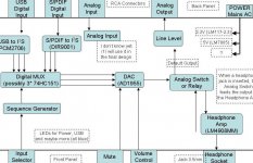
Hoping that very soon I will have tthe PCM working, can anyone suggest anything to add to my project?
I would like to experiment with a microcontroller and a LCD display. Perhaps I can display the input or the operating frequency or anything.
Any comments on that?
thank you very much
I'm going to put together a PCM2706 with an external DAC.
Hoping that very soon I will have tthe PCM working, can anyone suggest anything to add to my project?
I would like to experiment with a microcontroller and a LCD display. Perhaps I can display the input or the operating frequency or anything.
Any comments on that?
thank you very much
No, the maximum input voltage is 4V (this is a 3.3V chip). Use Vdd.Can I connect them onto VBUS (5V)?[/B]
Open any library once you are in the schematic capture. Then open a package and say "new" and give it a name. Then layout the package pads and save your work. Then open a symbol and again say "new" and then draw the symbol. The usual is to have inputs on the left side and outputs on the right side. Look at other symbols and packages in the library for examples.
Once you have created that package and the symbol, then open a device and again say "new" and give it a name. Then put the symbol you created into the device and then select the package you created and then connect all of the pins from the package to the symbol.
This will be a good learning experience for you on a good CAD tool. Refer to the help as needed.
BTW, the 2706 or 7 is a good part to use for a novice to get I2S output at 3.3V levels. I recommend that you drive a D/A chip that uses 3.3V input levels, such as the AD1955. The datasheet from analog devices has recommend output op-amp circuits.
This combo will sound pretty good once you figure out how to bypass Windows kmixer. I recommend Kernel Streaming on Vista or XP. You might be able to unmap the device on XP instead.
Steve N.
Thank you very much for your answer.
I started creating the new library last night. I stopped though because i didn't know what Grid to set.
According to the Eagle manual the Grid must be set to the correct value before put the pads and is different for each package.
From what i understand the grid should be set to the distance between the centres of two pads. From the datasheet this distance is 0.8mm.
Shall i set the grid to 0.82 ???
Do i need to set alternative Grid ??? If yes what ???
---------------------------------------------------------------------------
I thought that the PCM27xx are detected by windows automatically and i will not have to fiddle with windows.
I didn't know that i have to bypass the windows mixer ?
How difficult is that ? Is it essential or just a method to improve sound quality ? I don't understand. Could you please explain ?
Thank you very much
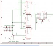
I'm useing the attached setup in order to switch between two I2S.
If you rememer, i'm completely new to electronic design so i would really apreciate your comments.
Is the 74HC151 acceptable for audio application?
Is this setup correct?
Shall i change this setup with 3 relays?
thank you
If you rememer, i'm completely new to electronic design so i would really apreciate your comments.
Is the 74HC151 acceptable for audio application?
Is this setup correct?
Shall i change this setup with 3 relays?
thank you
Attachments
audioengr said:Open any library once you are in the schematic capture. Then open a package and say "new" and give it a name. Then layout the package pads and save your work. Then open a symbol and again say "new" and then draw the symbol. The usual is to have inputs on the left side and outputs on the right side. Look at other symbols and packages in the library for examples.
Once you have created that package and the symbol, then open a device and again say "new" and give it a name. Then put the symbol you created into the device and then select the package you created and then connect all of the pins from the package to the symbol.
This will be a good learning experience for you on a good CAD tool. Refer to the help as needed.
BTW, the 2706 or 7 is a good part to use for a novice to get I2S output at 3.3V levels. I recommend that you drive a D/A chip that uses 3.3V input levels, such as the AD1955. The datasheet from analog devices has recommend output op-amp circuits.
This combo will sound pretty good once you figure out how to bypass Windows kmixer. I recommend Kernel Streaming on Vista or XP. You might be able to unmap the device on XP instead.
Steve N.
I'm a big believer in the AD1955. It's a dynamite DAC. The I/V from the Analog Devices eval board uses AD797 opamps. It's the best I/V I've heard for this chip. Very detailed yet not overly clinical and it's not bright sounding. The only downside of the 2706/7 is the limitation of 16/44 source content. You're right that the chip is easy to implement.
I've started working on an ethernet connection to the AD1955 using a Blackfin DSP running Linux. So fat I have Linux up and running on the DSP and have successfully communicated to both Mac's and PC's via ethernet. There is also a small web server running on this DSP which is great for user configuration of options. The Blackfin provides I2S output and controls the DAC in software mode. I'll post more information as the design becomes more practical.
-David
Hello, I had about three failed tries to make a PCM2706 work.
I'm using the Figure 33 on the page 29 of the datasheet (bus powered, internal dac). A copy is attached.
I would like to ask, what am i supposed to do with the pins 4, 5, 6, 7, 8, 11, 18 and 19. They are all Function and HID pins.
If i don't want to use those functions, can i just leave them open?
If I want to use those functions where am i suppose to connect this labeled suspend arrow showing in figure 33?
Thank you very much.
Attachments
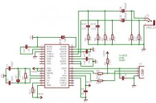
I would like to ask, what am i supposed to do with the pins 4, 5, 6, 7, 8, 11, 18 and 19. They are all Function and HID pins. If i don't want to use those functions, can i just leave them open?
Thats a bad idea when working with logic level devices. Either connect them to Vdd or ground. Page 7 of the datasheet explains the function (active high or low).
- Status
- This old topic is closed. If you want to reopen this topic, contact a moderator using the "Report Post" button.
- Home
- Source & Line
- Digital Line Level
- USB based DAC project