Another thought. Maybe we have two issues at work here.
The BA4560 (I had to look up the RC4560 opamp to get this) has a high drive capability, twice that of the LM4562. I wonder if the impedance of the filter network is just loading the opamp output stage too much. That distortion looks like an output stage loaded to heavily. So you may have to use the 4560 where originally fitted.
The other issue is the PSU loading with all those LM4562's. They do seem to be loading the rails and causing a lot of high frequency hash on the supplies.
mooly,
as of the moment the only lm4562 remaining are the ones @ the output stage. i have another 2xs here, stock. i opened it up and checked the opamps, the highpass section actually had a ba4558 and a ba4560 @ the hipass output. i mentioned earlier it had 2 ba4558. i was wrong.
however, it made sense. i removed the 4562 @ the highpass output and replaced the ba4560. the waveform came clean again.
unfortunately i noticed that at the lowpass section 1khz is clean but as i approach 4khz, the distortion starts to show up again. i was using 3.5khz as the cutoff that time so i thought that may be the cause. however it still is the same even if i changed the cutoff frequency beyond 4kHz.
now, on to the filter section. when i swapped the 4558 to 4562, distortion shows up at the outputs even @ 1khz on the lowpass section that's why i reinstalled the 4558.
here's a higher resolution (somewhat
 ) of the entire board. maybe you can make something out of the layout.
http://i123.photobucket.com/albums/o283/bzhei/2xsboard.jpg
btw, the function of the product is actually an active crossover AND line-driver. that may explain the use of ba4560.
my PSU filter caps are stock. do you think it could help if i swap them out to higher quality ones? i have Panasonics here but didn't want to install them until i get the op-amps working properly. i also have silmic IIs for the signal outputs but didn't install them for the same reason.
Thanks for the pic.
I don't think changing PSU caps is going to make a lot of difference tbh
It's very strange is all this... so many things seem to be going on. It's difficult to in not knowing the signal levels.
Are you sure your LM4562's are genuine ?
As so much has gone on with this I might be tempted to initially fit IC sockets and start again with new IC's that are known good ones. Do you have a record of the original IC type (so you are 100% sure of what was fitted where). Even if it means refitting all the original types and then measuring and confirming the performance, then swap the IC's one at a time.
We've no "baseline" to work to on this.
mooly,
my friend was the one who bought the opamps. i'll go ask him tomorrow.
i have sockets here that i could install in a while. i also have another 2xs that i can use as reference so i can fit the original ICs back together
so once i get the stock ICs and sockets in place, what do i measure first?
regarding the new opamps, it may take some time before i can get new ones since it is not being sold here locally. i have to order online and have it shipped here which usually takes 3-4 weeks.
can you recommend where i can get genuine ones? i may have to order it myself and get tl072 at the same time. i've seen them used in another more modern line driver so i guess it's a good choice also.
thanks for your assistance i really appreciate it
Don't know your location so can't really advise where to get components from. The general opinion seems that ebay should be avoided.
With sockets in place and all the original IC's fitted you need to first of all confirm that the unit works OK by listening to it.
Having confirmed it is OK you then have to measure the rails, then scope the rails and make a note of the noise/ripple etc. Thats useful info to have as power requirements of different IC will alter the noise on the rails... hopefully not much if we pick low power opamps.
Then apply a signal as you have been doing and confirm that the output on all the opamps is OK. Make a note of the signal frequency and amplitude and also any settings in the unit such as pots, switches etc.
Then replace each opamp one at a time starting at the input side and confirm the output on each opamp is the same as with the original type fitted. If the original begins to distort at say 6 volts peak to peak output then the replacement should be at least as good.
The TL072 should be fine to replace the 4558 types.
The OPA2134 is a possible choice for the 4560 as it has a good drive ability but I would say not for the 4558's as the power requirements stack up.
The TLE2072 could be the best choice for all if you can get them.
Please remember though that I haven't worked on this unit so am suggesting what I feel should work OK.
Is it worth posting a good close up of your LM4562's ? Might not reveal anything but you never know.
i don't know if this may help, i emailed a company in Malaysia a year ago regarding mods on audiocontrol units since they specialize in modding this brand as well as mcintosh. they offer them in stage 1 - stage 3.
stage 1 and 2 includes
-rectification stage improvement using ultrafast rectifying SiC diodes with zero recovery.
-switch mode power supply improvement
-larger reservoir caps + low esr audiophile grade caps
-analog stage improvement
stage 3 and further
-burr brown op-amp upgrade and others.
since the first stage is obviously focused on the power supply section and the op-amp upgrade is further down the upgrade path, maybe we really need to beef up the supply section in order to provide useable power to the op-amps. but of course, the company won't go into detail how and what particular components will be used.
Digi-Key parts should be OK
I think we have to go back to the beginning with all this and put all the original type IC's back (using sockets). You have to then confirm that the unit is OK before slowly changing parts one at a time and measuring along the way as I outlined above.
The power supply is suspect with regard to how much current it can supply for more power hungry opamps. One possible approach to prove that is to power the opamps from a separate lab PSU, or even batteries if a problem arises.
The mods you mention may or may not achieve much. All switching supplies need "fast" diodes and the ones fitted will be "fast". It wouldn't work and they would get hot if you had standard types fitted. So talking about fitting "ultrafast" is probably more marketing talk than anything else. High performance caps certainly help on switching supplies but as this is already a switching supply the caps fitted will be OK for purpose. Fitting high performance low E.S.R. types may make a small improvement by reducing noise but it's not a night and day difference.
BurrBrown opamps... the one that comes to mind is the excellent OPA2604 but there are many.
So my own feeling is that you have to go back to the unit in original stock form and start again measuring on each opamp as it is swapped and also keep detailed notes as you go.
See what the ripple on the rails is before swapping a particular opamp.
Does fitting a different opamp increase that ripple.
See at what point (signal amplitude and frequency) a particular opamp begins to distort.
Does a new opamp change those values.
Choose an opamp with good drive ability for the BA4560, this is one area the LM4562 is not as good.
hi mooly,
i did my tests the way you told me.
the stock ICs operated well.
btw, where do i exactly reference my ground when taking AC ripple voltage? i did two measurements just to be sure.
with the stock ICs. here are the AC ripple and rail voltages.
referenced to transformer secondary center tap:
BA4560
1kHz signal input
Vcc = +48mVp-p
Vee = -56mVp-p
rail voltage @ diode output = +15.43/-15.3
rail voltage @ first BA4560 (input section) op-amp = +15.3/-15.3
8kHz signal input
Vcc = +88mVp-p
Vee = -88mVp-p
same rail voltage @ both diode and op-amp
when i reference the ground to the crossover's negative terminal, the Vcc and Vee is very high @ +1.080Vp-p and -1.040Vp-p.
after measuring, i swapped out the first BA4560 at the input section with an LM4562. here are the measurements. still referenced to transformer secondary center tap.
LM4562
1kHz signal input
Vcc = +36mVp-p
Vee = -44mVp-p
rail voltage @ diode output = +15.45/-15.45
rail voltage @ LM4562 = +15.37/-15.37
8kHz signal input
Vcc = +80mVp-p
Vee = -80mVp-p
same rail voltages
after that, i checked the signal path using 8kHz signal since that frequency shows the most distortion.
BA4560
signal input sinusoidal(non-inv pin) = 9.4Vp-p
signal output = 24.4Vp-p
signal output wave = sinusoidal
LM4562
signal input sinusoidal(non-inv pin) = 9.4Vp-p
signal output = 22.4Vp-p
signal output wave = distorted, almost triangular like.
because the first op-amp produces a distorted signal and lower voltage output, the rest of the op-amps gets lower voltage too.
i then check @ what frequency the signal starts to distort. @ 400Hz, there is already a tiny amount of distortion visible in the waveform. the input voltage is still 9.4Vp-p. i need to drop the input voltage to 1.6Vp-p to clean it out.
i also tried to put all LM4562 in place and check rail voltage. it's the same as the stock ICs in place.
hi mooly,
i did my tests the way you told me.
the stock ICs operated well.
So this shows the unit as as it should with original parts fitted.
btw, where do i exactly reference my ground when taking AC ripple voltage? i did two measurements just to be sure.
The signal path should have a common ground. To be sure I would use a ground near each IC you are measuring on. If an opamp input is tied to ground via a resistor etc then that point has to be good for measurement as it is the ground relevant to that IC.
with the stock ICs. here are the AC ripple and rail voltages.
referenced to transformer secondary center tap:
BA4560
1kHz signal input
Vcc = +48mVp-p
Vee = -56mVp-p
rail voltage @ diode output = +15.43/-15.3
rail voltage @ first BA4560 (input section) op-amp = +15.3/-15.3
8kHz signal input
Vcc = +88mVp-p
Vee = -88mVp-p
same rail voltage @ both diode and op-amp
This shows that as the opamp works harder (and draws more current) the ripple voltage increases.
when i reference the ground to the crossover's negative terminal, the Vcc and Vee is very high @ +1.080Vp-p and -1.040Vp-p.
The only obvious reason for this is the impedance of the grounds at high frequencies as this is important for high frequency ripple with switching supplies. I wouldn't worry over that at all. The design of the unit should be correct with respect to grounding and what is referenced to where.
after measuring, i swapped out the first BA4560 at the input section with an LM4562. here are the measurements. still referenced to transformer secondary center tap.
LM4562
1kHz signal input
Vcc = +36mVp-p
Vee = -44mVp-p
rail voltage @ diode output = +15.45/-15.45
rail voltage @ LM4562 = +15.37/-15.37
8kHz signal input
Vcc = +80mVp-p
Vee = -80mVp-p
same rail voltages
after that, i checked the signal path using 8kHz signal since that frequency shows the most distortion.
BA4560
signal input sinusoidal(non-inv pin) = 9.4Vp-p
signal output = 24.4Vp-p
signal output wave = sinusoidal
LM4562
signal input sinusoidal(non-inv pin) = 9.4Vp-p
signal output = 22.4Vp-p
signal output wave = distorted, almost triangular like.
because the first op-amp produces a distorted signal and lower voltage output, the rest of the op-amps gets lower voltage too.
i then check @ what frequency the signal starts to distort. @ 400Hz, there is already a tiny amount of distortion visible in the waveform. the input voltage is still 9.4Vp-p. i need to drop the input voltage to 1.6Vp-p to clean it out.
i also tried to put all LM4562 in place and check rail voltage. it's the same as the stock ICs in place.
All these results seem to show that the LM4562 can not drive the filter networks sufficiently... it's just a lack of drive current ability. That is backed up by the triangular distortion as the opamp just limits.
So it looks like the answer is to either stick with the original devices or use something with really good drive ability. The big question is what ?
I would still go with something like the TLE2072 but you would have to just try one to see. I can't guarantee it
It's quite an unusual scenario where a "high current" opamp is really needed but that does seem to be the problem here.
thanks mooly.
now i think i'm going to shop for new op-amps.
when you say good driving ability, what exactly will i be looking for @ the data sheet? i mean, what is the term for it? since some data sheets use different terms for some data. what other specs will i be looking at? i noticed in digi-key there's this 'voltage input offset'. is this also relevant? i'm browsing over at digikey since it's easier to compare opamps as some datasheets use different terms.
my plan would be to purchase 3 op-amps of each particular kind, swap them out to the 3 ba4560s in the circuit and scope if the output is the same. does that make sense?
It's the ability to drive low impedance loads at full voltage output. Most modern opamps are specified as being able to drive 600 ohms fully. In the data sheets a clue is in the maximum available output current. You also have an additional problem of a PSU that is very limited in output and so that means the IC's used must also have a low quiescent current as well as good drive.
For example if you can draw say 100 milliamps max from the supply before problems occur and you have 10 opamps that draw say 4 ma each then you are already drawing 40 ma. Drive the opamps hard and there is only 60 ma "left" for the opamps to pump into the filter networks. And that is OK.
Now swap the opamps for some that draw say 8 ma and you are already pulling 80ma from an 100ma supply. So there is nothing left when the opamps need more current to feed the filters.
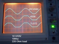
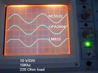
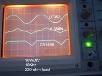
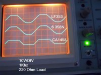
Theory into practice
Different opamps when resistively loaded.
For example if you can draw say 100 milliamps max from the supply before problems occur and you have 10 opamps that draw say 4 ma each then you are already drawing 40 ma. Drive the opamps hard and there is only 60 ma "left" for the opamps to pump into the filter networks. And that is OK.
Now swap the opamps for some that draw say 8 ma and you are already pulling 80ma from an 100ma supply. So there is nothing left when the opamps need more current to feed the filters.
Theory into practice
Different opamps when resistively loaded.
Attachments
thanks for the photos mooly,
i just ordered some tle2072 and 2604s. it'll be a few weeks before it arrives.
out of curiousity though, do you think it's possible to rework the surrounding circuit, change resistor/cap values to make the filter network easier on the 4562? i have two of this active crossovers and 22 lm4562s and i'm thinking of trying to rework the other one around the 4562.
the way this crossover works is through a programmable/removable DIP module which you can build yourself. that way, i can compensate for the effects on crossover points caused by the other circuit changes.
Reworking the filters is probably no easy task as there could be interactions unless everthing was done. I think that's too ambitious without a full circuit in front of you and checking the response of one modded channel against the other unmodded one. Far easier to get the opamps right really. You would need to scale all the filters, which is no easy task tbh when you are perhaps looking for non standard caps to use.
The OPA2604 really is a great opamp sonically, and it's always been one of my favourites.
Keep us updated on how it all goes...
The OPA2604 really is a great opamp sonically, and it's always been one of my favourites.
Keep us updated on how it all goes...
I just a couple of days ago mounted an LF356 I had laying around - probably over 30 years old - in stead of OPA 2134 by mistake in an active filter I am designing. Only 1 in 4 opamps total. Filter slope was completely off on the low end, distortion was > 1 %, and before I could run over to the scope, I realized what happened. Put in a OPA 2134 and filterslope matched the design, THD+N became < 0.02%. So this is what happens when you put just another opamp, might even be a better one, in an active filter that was designed (calculated verified with measurements) to work with a specific device. For the buffer stages you might do a bit of rolling, but I would keep the filter part as is, or be prepared for significant redesign.
vac
vac
I just a couple of days ago mounted an LF356 I had laying around - probably over 30 years old - in stead of OPA 2134 by mistake in an active filter I am designing.............
vac
The LF356 is a single, OPA2134 a dual
or maybe you mean you tried it in a breadboard situation for one half of an OPA2134.
Last edited:
The LF356 is a single, OPA2134 a dual
or maybe you mean you tried it in a breadboard situation for one half of an OPA2134.
Well, that would explain it even better; it was accidentally soldered in place of an OPA2134. Just some old opamp that wound up in the bin with the 2134's. However, I found that for filter applications, LTSpice is pretty sensitive for the opamp being used, and even then, calculated and simulated responses will deviate from actual measurements. Hence I think the gist of my advise still holds true.
vac
can't seem to shake the thought off of an unstable LM4562. and i still have a few weeks to wait for the op-amps to arrive so i decided to do some more testing.
this time i did it in a breadboard. it might or might not reveal something but just want to share. in the actual board, the first op-amp already distorts it's output so i figured if i can make the first op-amp put out a clean signal, then maybe i can try to slowly work around the other op-amps.
this is the schematic for the first op-amp which i sketched to guide me in replicating it in the bread board it also shows the second op-amp. C1 is so tiny but i can make up JDC102 being labeled. C2 and C3 is 2A 220.
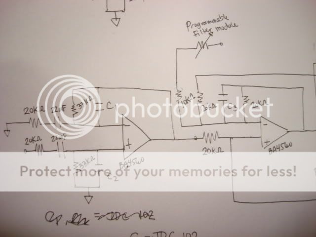
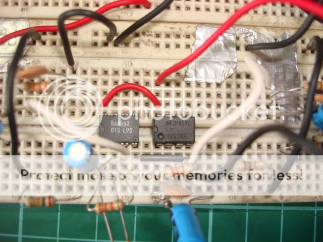
i quickly rigged up the BA4560 and LM4562 in the breadboard so i can compare their outputs. both opamps operate independently from each other
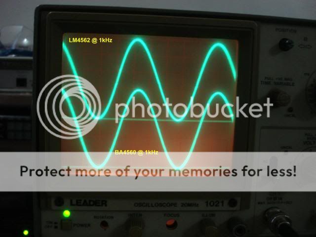
i borrowed my friend's dual trace scope so i can make comparisons easier.
here are the waves @ 1kHz. taken @ pin1 of both op-amps
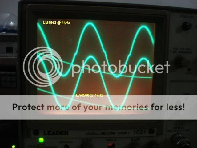
@ 4kHz
@ 8kHz
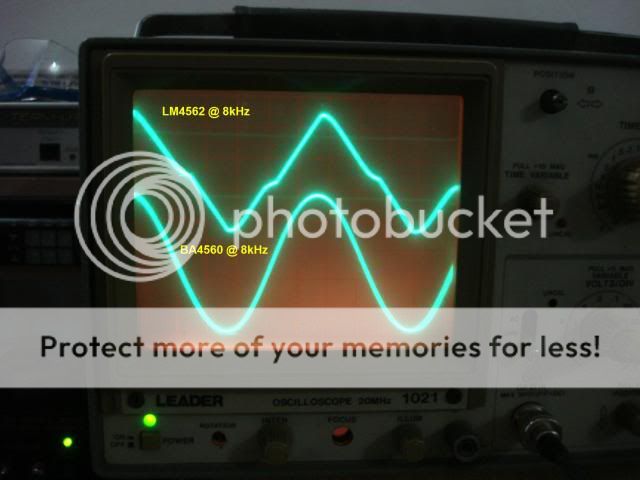
these are the only two op-amps powered so i guess the power supply is no issue here?
by the way, what's the weird line showing up at the scope together with the waveform? i don't recall seeing that in my scope.
this time i did it in a breadboard. it might or might not reveal something but just want to share. in the actual board, the first op-amp already distorts it's output so i figured if i can make the first op-amp put out a clean signal, then maybe i can try to slowly work around the other op-amps.
this is the schematic for the first op-amp which i sketched to guide me in replicating it in the bread board it also shows the second op-amp. C1 is so tiny but i can make up JDC102 being labeled. C2 and C3 is 2A 220.
i quickly rigged up the BA4560 and LM4562 in the breadboard so i can compare their outputs. both opamps operate independently from each other
i borrowed my friend's dual trace scope so i can make comparisons easier.
here are the waves @ 1kHz. taken @ pin1 of both op-amps
@ 4kHz
@ 8kHz
these are the only two op-amps powered so i guess the power supply is no issue here?
by the way, what's the weird line showing up at the scope together with the waveform? i don't recall seeing that in my scope.
Last edited:
That's really interesting...
Your circuit doesn't show a particularly tough load. C1 is for stability and could be as low as 4.7pf.
Those LM4562's are starting to look highly suspect. Have you tried a 4558 in the breadboard for interest.
The first opamp stage as drawn is a simple amp... the 4562 should be brilliant here... something is very wrong I think.
The scope line could be an artifact of the camera (seeing something thats faint). It could be the "flyback" trace of the scope or does the scope have an expanded 3rd expanded trace, and it's showing part of the waveform at greatly expanded form.
- Status
- This old topic is closed. If you want to reopen this topic, contact a moderator using the "Report Post" button.
- Home
- Source & Line
- Analog Line Level
- upgrading active xover with LM4562