Sorry for the duble post, but in the mean time I documented myself more about transformers an line matching impedance, so I am looking to buy the Cinemags ")
My only questions ramain:
1)what is the output impedance of the buffer used in this topic
2) in the Cinemags datasheet it says " It is designed to operate well when driven by 600 ohm lines" - that it means that the optimal buffer output impedance should be 600 ohm?
My only questions ramain:
1)what is the output impedance of the buffer used in this topic
2) in the Cinemags datasheet it says " It is designed to operate well when driven by 600 ohm lines" - that it means that the optimal buffer output impedance should be 600 ohm?
Broskie cathode follower
Hi All,
I hope you don't mind me chipping in on this thread, but I have been following it with interest as I purchased a single board DDDAC a few months ago.
Although I have the latest version 4.4 boards (Blue main board and Tent DAC board) I have been looking at options regarding using both sides of the balanced output. (I currently use the basic setup with the +ve output only in single ended mode)
The cost of the Cinemags, plus 3 more boards to drive them properly seems a little excessive, and having a huge aversion to any silicon in the analogue side of the signal path I started looking at alternatives using a tube buffer stage. A number of people have mentioned the Broskie cathode follower in other posts / threads, and so to cut a long story short, I built one, using the design that John has on his website, and a simple regulated PSU off the web.
The results are absolutely superb. Much more detail in general and a significant increase in bottom end weight and control. This seems to me to be a really cost effective solution to some of the issues debated here, and I would encourage anyone who has the confidence to work with high voltage tube circuits to give it a go. Although I haven't heard a fully tricked out DDDAC with multiple boards and cinemags I am delighted with the improvements the BCF has generated and would be more than happy to provide further details if anyone would like them
Cheers,
Steve.
Hi Simon,
Thanks for the note. I was sure I had seen comment to the fact that more than one board is needed for the cinemags, but happy to be corrected if 1 is sufficient.
The BCF user guide can be found here -
http://glass-ware.com/User_Guides/BCF 9-Pin.pdf
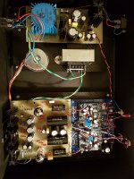
Photo of my DAC below.
I am already thinking about stage 2 on this, as I ideally need a little more gain, so am looking at the Broskie Unbalancer which is basically the BCF with a differential gain block on the front. Will let you know how it goes.
Cheers,
Steve
Thanks for the note. I was sure I had seen comment to the fact that more than one board is needed for the cinemags, but happy to be corrected if 1 is sufficient.
The BCF user guide can be found here -
http://glass-ware.com/User_Guides/BCF 9-Pin.pdf
Photo of my DAC below.
I am already thinking about stage 2 on this, as I ideally need a little more gain, so am looking at the Broskie Unbalancer which is basically the BCF with a differential gain block on the front. Will let you know how it goes.
Cheers,
Steve
Attachments
Hi Steve and others
I am very interested in you experience with the BCF/unbalancer. I have an older DDDac(without Tent reg) and need to make a decision on the path ahead.
I run it into a single-ended hybrid integrated amp and it has served me well over the past 2 years but in comparison to a commercial NOS pcm1704 dac(aqua La Scala) it just doesn't have the verve and drive of the higher output unit from Italy. A bit higher output might come in handy as well as the ability to convert the balance to the SE output.
I use the DDDac without output caps and one of my concerns is the signal caps of the Valve buffer?
I also wonder what valves you use, ecc82 and ecc99 would be my 1st stab if I had to make a call on it?
Thanks
Stefan
Hi there, quick question. Bit late to the party, but I wonder if anyone could help with this. I have a few jfets 2sk246bl. What would be the negative side effects of using the bl version over the y version for the ccs circuit? I can dial both in, I would just need some more resistence right?
http://pdf.datasheetcatalog.com/datasheet/toshiba/1031.pdf
http://pdf.datasheetcatalog.com/datasheet/toshiba/1031.pdf
IMO it is important to upgrade the RLoad resistors above the stock Dale RN's. The TX2575 z-foils and Rhopoints are reported to be the best, but are expensive and 133ohms are special order. The Tantalums are a more reasonable priced upgrade but the closest I was able to get was 2X270ohms. The Susumu RG SMD transistors have greater clarity than the Dale RN's and sound at least as good as the Tantalums to me.
What I can do is provide ten 0.1% 270ohm SMD Susumu 1206 RG resistors plus a 2cm X 4cm piece of adhesive backed tinned copper sheeting for SMD installation for $8 plus shipping in an envelope. No extra shipping if mailed with other parts order. Paralleling 270 ohm resistors provides 135 ohms for a single board DAC. The large Susumu RG is not available in 133 ohms, but this difference should not be audible. The purist can add a 3rd 10K resistor in parallel to get 133.2 ohms. Four 10K SMD resistors add $3 to the price. For 2 Board DACs needing 66-67 ohms - three 200 ohm SMDs in parallel equal 66.7 ohms. Cost for 14 0.1% 200 ohm Susumu's and copper sheeting piece is $11 plus shipping. The wattage load for a 4+ board DAC is too much for SMD resistors. PM or email me if interested.
Attached is a picture of the Susumu RG resistors installed in the Rload position using the adhesive backed tinned copper sheeting. Both sides measure 134.9 ohms which should minimize DC offset. There is room for 3 SMD resistors in parallel if needed. Looks more secure than using wires to bridge the gaps.
Hello,
I don't understand this statement.
I have 4 boards and intend to use 6 200 ohm Susumu 1206 RG. If 3 270 ohm resistors in parallel could drive 2 boards, why would't 6 parallel resistors be enough for 4 boards? What I am missing?
Thank you !
Ok, also late at the party. I built the ccs with the 2sk246y.
I made it on a protoboard and checked it 4 times. I'm getting 2.4V when connected to lab power supply and in my DAC but no current anywhere I connect my multimeter.
I'm not building this on a DDDac but in a different 1x PCM1794 DAC and it worked but I can't say that it was better than the 6k resistor.
Anyone have a clue? Am I doing something wrong?
Okay guy's, I think I feel comfortable enough to make this entry so here we go
I've been on an audio quest for some time. It started in late 2014 with a "simple" question: "What is a loudspeaker?" While such a question might seem trivial to many of you,
for someone who had no experience in engineering and designing loudspeakers, it is an important question which leads to multiple ways to answer it. While this thread is not
about loudspeakers, I just wanted to share the beginning of why I am here and what I am doing.
I came to a point, about 1½ year ago where I realized that in order to properly evaluate my loudspeaker designs, I need reference level equipment. Since I have a limited budget
and can't afford stuff that would cost me tens of thousand dollars, I figured I could spend some time reading and researching what is worth chasing down, and while I have been
rather successful doing so for power amplifiers, what remained was the preamplifier, d/a converter and music server. That's when I ran into the Burr-Brown PCM1794 Delta-Sigma DAC chip
which seams to very popular and can be found in many converters and one of these converters is the DDDAC 1794 NOS designed by Doede Duama. I was initially going to build
the Yamamoto YDA-01B with a tube output stage, but reading some reviews about this paralleled DAC made me curious, curious enough to wanting one for myself.
But it's not a perfect DAC and some of the "flaws" was covered by another member who also designed his own improved version. This edition was covered earlier in the thread and was
designed by Enrico. And just like Enrico, I wanted some improvements, ontop of what Enrico already did, so I started studying components and what's important when designing PCB's
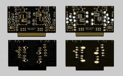
and arrived at what you can see attached bellow. It's still early day's and the main-board as well as the PSU need to be designed and optimized, but I can share some of the structure
and components which is part of the project and DAC module (seen in the attachment).
The DAC module.
- Separate Left and Right analog & digital power supply.
- Separate left and right analog & digital gnd.
- Separate A.D LT3045 LDO voltage regulator for the analog & digital side of the PMC1794 d/a chip. There ar 4 LDO's per card.
- Each PMC1794 and LT3045 is protected by Laird Board Level Shield. That is the weird rectangles you see on the front.
- Resistor are Susumu RG 1206 thin film.
- Bypass capacitors are:
- Each 3.3V & 8V line has test points for monitoring, placed at the top edge for ease of access when the cards are installed.
- As you can see, this PCB feature the card edge connector style for easy installation and removal if the card need service or repair.
I will give the main board and PSU a similar treatment as I did for the dac module, so expect more to come as these are finalized. The full realization of the project will take a few months
as it also need it's own bespoke chassis.
Comments, advice and general feedback is welcome
This project is a collaboration with another forum member: Robin De Wolf - thanks a million for the cool ideas, this project would be half of what it will be without you
I've been on an audio quest for some time. It started in late 2014 with a "simple" question: "What is a loudspeaker?" While such a question might seem trivial to many of you,
for someone who had no experience in engineering and designing loudspeakers, it is an important question which leads to multiple ways to answer it. While this thread is not
about loudspeakers, I just wanted to share the beginning of why I am here and what I am doing.
I came to a point, about 1½ year ago where I realized that in order to properly evaluate my loudspeaker designs, I need reference level equipment. Since I have a limited budget
and can't afford stuff that would cost me tens of thousand dollars, I figured I could spend some time reading and researching what is worth chasing down, and while I have been
rather successful doing so for power amplifiers, what remained was the preamplifier, d/a converter and music server. That's when I ran into the Burr-Brown PCM1794 Delta-Sigma DAC chip
which seams to very popular and can be found in many converters and one of these converters is the DDDAC 1794 NOS designed by Doede Duama. I was initially going to build
the Yamamoto YDA-01B with a tube output stage, but reading some reviews about this paralleled DAC made me curious, curious enough to wanting one for myself.
But it's not a perfect DAC and some of the "flaws" was covered by another member who also designed his own improved version. This edition was covered earlier in the thread and was
designed by Enrico. And just like Enrico, I wanted some improvements, ontop of what Enrico already did, so I started studying components and what's important when designing PCB's
and arrived at what you can see attached bellow. It's still early day's and the main-board as well as the PSU need to be designed and optimized, but I can share some of the structure
and components which is part of the project and DAC module (seen in the attachment).
The DAC module.
- Separate Left and Right analog & digital power supply.
- Separate left and right analog & digital gnd.
- Separate A.D LT3045 LDO voltage regulator for the analog & digital side of the PMC1794 d/a chip. There ar 4 LDO's per card.
- Each PMC1794 and LT3045 is protected by Laird Board Level Shield. That is the weird rectangles you see on the front.
- Resistor are Susumu RG 1206 thin film.
- Bypass capacitors are:
- Panasonic OS-CON Polymer (SVPG) - 15uF - as the main bulk capacitor on the analog side.
- Panasonic SP-Cap (LR) 3-terminal for very low ESL - 68uF as the main bulk capacitor for the digital side. 50% lower ESL than your common 2-terminal capacitor.
- These are accompanied with a MLCC of the X2Y variant which is also a low ESL variant. Values here are 1.0uF and 0.1uF. The MLCC is placed very close to the operational pin of the PMC1794.
Which you can see on the backside of the PCB.
- Each 3.3V & 8V line has test points for monitoring, placed at the top edge for ease of access when the cards are installed.
- As you can see, this PCB feature the card edge connector style for easy installation and removal if the card need service or repair.
I will give the main board and PSU a similar treatment as I did for the dac module, so expect more to come as these are finalized. The full realization of the project will take a few months
as it also need it's own bespoke chassis.
Comments, advice and general feedback is welcome
This project is a collaboration with another forum member: Robin De Wolf - thanks a million for the cool ideas, this project would be half of what it will be without you
Attachments
Hi ... A suggestion could be to dismount the CCS board and connect the pin going to pin 20 (Iref) to a 2.4 VDC voltage source and check if the CCS works as intended (may also be e.g. a LiFePO4 battery). And, if you have been soldering near the adjacent pins then check that none of the pins has been shorted.
Cheers,
Jesper
Cheers,
Jesper
Last edited:
I had some problems with mine. Checked the schematic and it was correct. But I rotated the part 180 degrees on my board and it worked like it should. I don't know why but it did. Maybe something to do with the internals because I thought they worked both ways. Seemed it didn't.
Which one is the right one?
Well, they basically are both right - they just do the same (adjusting the voltage drop from the JFET's gate to source and hence the drain current) in different ways. The right one is the one Doede Douma (DDDAC's creator as you may know) shows in his schematic.
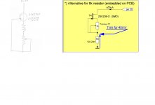
Anyway, personally I would adjust the CCS to the right current, unsolder it and replace the trimmer and 100 ohm resistor with one fixed resistor (can be less thermal drift, smaller (EMI reduction), and closer to the underlying GND plane). Just my thought about this.
Susumu RG or RR1220 could be resistors to use (but there are of course other options).
Cheers,
Jesper
Okay guy's, I think I feel comfortable enough to make this entry so here we go
I've been on an audio quest for some time. It started in late 2014 with a "simple" question: "What is a loudspeaker?" While such a question might seem trivial to many of you,
for someone who had no experience in engineering and designing loudspeakers, it is an important question which leads to multiple ways to answer it. While this thread is not
about loudspeakers, I just wanted to share the beginning of why I am here and what I am doing.
I came to a point, about 1½ year ago where I realized that in order to properly evaluate my loudspeaker designs, I need reference level equipment. Since I have a limited budget
and can't afford stuff that would cost me tens of thousand dollars, I figured I could spend some time reading and researching what is worth chasing down, and while I have been
rather successful doing so for power amplifiers, what remained was the preamplifier, d/a converter and music server. That's when I ran into the Burr-Brown PCM1794 Delta-Sigma DAC chip
which seams to very popular and can be found in many converters and one of these converters is the DDDAC 1794 NOS designed by Doede Duama. I was initially going to build
the Yamamoto YDA-01B with a tube output stage, but reading some reviews about this paralleled DAC made me curious, curious enough to wanting one for myself.
But it's not a perfect DAC and some of the "flaws" was covered by another member who also designed his own improved version. This edition was covered earlier in the thread and was
designed by Enrico. And just like Enrico, I wanted some improvements, ontop of what Enrico already did, so I started studying components and what's important when designing PCB's
and arrived at what you can see attached bellow. It's still early day's and the main-board as well as the PSU need to be designed and optimized, but I can share some of the structure
and components which is part of the project and DAC module (seen in the attachment).
The DAC module.
- Separate Left and Right analog & digital power supply.
- Separate left and right analog & digital gnd.
- Separate A.D LT3045 LDO voltage regulator for the analog & digital side of the PMC1794 d/a chip. There ar 4 LDO's per card.
- Each PMC1794 and LT3045 is protected by Laird Board Level Shield. That is the weird rectangles you see on the front.
- Resistor are Susumu RG 1206 thin film.
- Bypass capacitors are:
- The variable resistor is Vishay Accutrim 1240 foil type.
- Panasonic OS-CON Polymer (SVPG) - 15uF - as the main bulk capacitor on the analog side.
- Panasonic SP-Cap (LR) 3-terminal for very low ESL - 68uF as the main bulk capacitor for the digital side. 50% lower ESL than your common 2-terminal capacitor.
- These are accompanied with a MLCC of the X2Y variant which is also a low ESL variant. Values here are 1.0uF and 0.1uF. The MLCC is placed very close to the operational pin of the PMC1794.
Which you can see on the backside of the PCB.
- Each 3.3V & 8V line has test points for monitoring, placed at the top edge for ease of access when the cards are installed.
- As you can see, this PCB feature the card edge connector style for easy installation and removal if the card need service or repair.
I will give the main board and PSU a similar treatment as I did for the dac module, so expect more to come as these are finalized. The full realization of the project will take a few months
as it also need it's own bespoke chassis.
Comments, advice and general feedback is welcome
This project is a collaboration with another forum member: Robin De Wolf - thanks a million for the cool ideas, this project would be half of what it will be without you
Hi Oneminde,
just checking to be 100% sure.... These boards are ONLY for private use and you alone, right?
using my name on this board "DDDAC 1794 NOS 2021Version" is of course a no-go, should they every pop up somewhere it looks like it is coming from me. If you build your own car, you cannot put a "Mercedes" star on the hood
If you want to sell these, better contact me first!
thanks !
doede
Hi Doede,
Oneminde decided to pursuit another dac design a few months ago. I will be picking it up again (when I have the time) I am a happy owner of an original DDDAC two decker and of course will use another name if I proceed.
It was a joint effort by us with no intention of selling at all. For me it was and still is quite a learning journey.
If there is any discomfort by this, please let me know.
Best regards,
Robin
Oneminde decided to pursuit another dac design a few months ago. I will be picking it up again (when I have the time
) I am a happy owner of an original DDDAC two decker and of course will use another name if I proceed.It was a joint effort by us with no intention of selling at all. For me it was and still is quite a learning journey.
If there is any discomfort by this, please let me know.
Best regards,
Robin
Last edited:
- Home
- Source & Line
- Digital Line Level
- Upgraded Single Board PCM1794 NOS DDDAC