if 9 volt item failed to work, 6L6 would not have said it would.
Here's what i can speak to with certainty -
When using IRF Mosfets and the original 5.1V zener, I couldn't get very much bias; I don't remember how much, but with the pot maxed out the heatsinks were not even warm. The change to the 9.1V zener got the amp biasing as designed.
There may certainly be a better answer, such as a 6.2V zener or a pair of blue LED in series. I haven't experimented past getting it working.
If a 6 or 7V zener, or a change in the pot value makes things work better, I'm all for updating my guide.
I can say with certainty that using anything over 7V zeners for the IRF mosfets in the original circuit introduces bias instability. It ends up fluctuating as a function of the input signal (or more accurately, whatever ripple is in yr power supply).. Anything less than ~6V will make it difficult to bring the bias up to an adequate level. I used 6.1v zeners while keeping everything else the same and I have no problems biasing up to ~1.2A but you may need a higher voltage zener (or lower R7/8 values) if you'd like to go bigger.
Last edited:
If the 10k resistor R7 and R8 is changed to between 3.3k and 5k then all Zeners between 5.1V and 9.1V should operate correctly.If a 6 or 7V zener, or a change in the pot value makes things work better, I'm all for updating my guide.
This will provide the most flexibility for builders.
Last edited:
Continuing with 2pico's example above, I think the bias would be somewhat
sensitive to the voltage rails.
If your rail is V_0=23V, then you basically have 23/3 volts
across the 5K trimmer. You adjust the trimmer to set the bias. Let say you
end up with Vgs = 4.6 V. So the trimmer reduces the voltage to 0.6x the input
value. In other words, the Vgs ~ 0.6 * V_0/3.
Now, imagine if the rail voltage is not perfectly stable and it has gone up to 24V,
say caused by AC mains variation, then the Vgs ~ 0.6 * 24 /3 = 4.8V. I imagine
this is enough to cause a noticeable drift in bias.
Dennis
Correct.
When using IRF Mosfets and the original 5.1V zener, I couldn't get very much bias; I don't remember how much, but with the pot maxed out the heatsinks were not even warm.
I'm curious what might have caused this. Perhaps a combination of
high Vgs mosfet and out of spec zener or insufficient current to bring the
zener up close to 5.1V?
Anyone want to hazard a guess?
Dennis
Zeners can be left out.
A simple, one JFET 1.2mA CCS can supply the 5k trimm-pot and the bias can be easily set in 0 - 6 V range.
Additional 40 dB of PSRR is a bonus with this solution.
A simple, one JFET 1.2mA CCS can supply the 5k trimm-pot and the bias can be easily set in 0 - 6 V range.
Additional 40 dB of PSRR is a bonus with this solution.
I'm curious what might have caused this. Perhaps a combination of
high Vgs mosfet and out of spec zener or insufficient current to bring the
zener up close to 5.1V?
Anyone want to hazard a guess?
Dennis
I have no guess.
All I know, I can bias the F6 up to 1.7A with a 5.6v zener and Vishay 240 mosfets.
6.2V brings it way above 2A.
A 7.5V zener will probably release the magic smoke if not careful...

Dennis Hui said:I'm curious what might have caused this. ...
high Vgs mosfet ?
Anyone want to hazard a guess?
That's the most likely cause. Vgs of these devices can vary by more than a volt, and the Mosfet I had must have been on the high side.
FWIW, I placed a simple red LED in series with the 5.1V zener, in essence making a 7V zener, and it worked perfectly.
ZenMod said:boyz , don't obsess with few parts
Right? I agree.
No obsession on my part...just curious whether we missed something obvious
or subtle.
I do like Juma's solution.
FWIW, I didn't want to order more parts so I used 9.1V zener and 3.3K resistor.
Now if only I have time to finish the darn thing... 🙂
Thank you all.
Dennis
or subtle.
I do like Juma's solution.
FWIW, I didn't want to order more parts so I used 9.1V zener and 3.3K resistor.
Now if only I have time to finish the darn thing... 🙂
Thank you all.
Dennis
The Master has several times insisted that selecting active parts is more important than selecting resistor or caps or...No obsession on my part...just curious whether we missed something obvious
or subtle.
...
Maybe putting that zener there was a subtle way to tell us that low Vgs works better in this amp
[emoji41]

My associate and I are jointly putting this F5 to F6 Upgrade together
he is a lot better at soldering than me.
So the upgrade build has begun
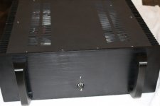
Before I start to show off the upgrade section its is best to start with the before photos that shows the F5 and then continue to the finish as an illustrated build of the F5 to F6 Upgrade progress
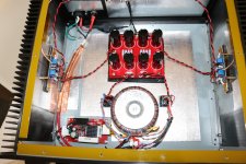
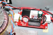
We have also decided to remove the soft start section and replace it with a resistor ( but keep it on hand just in case we want to install it again )
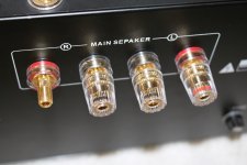
Please note my favorite speaker terminals that I have used on this Amp and others and also on my crossovers
they are available form Speakerbug - http://speakerbug.com.au/index.php?route=product/product&path=61&product_id=307
So all these photos are of the current F5 still intact
he is a lot better at soldering than me.
So the upgrade build has begun
Before I start to show off the upgrade section its is best to start with the before photos that shows the F5 and then continue to the finish as an illustrated build of the F5 to F6 Upgrade progress
We have also decided to remove the soft start section and replace it with a resistor ( but keep it on hand just in case we want to install it again )
Please note my favorite speaker terminals that I have used on this Amp and others and also on my crossovers
they are available form Speakerbug - http://speakerbug.com.au/index.php?route=product/product&path=61&product_id=307
So all these photos are of the current F5 still intact
Attachments
Last edited:
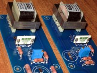
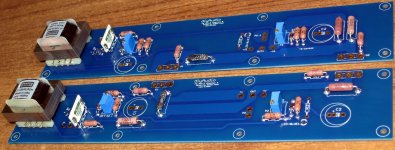
So the Upgrade has begun with populating the PCB's from the DIY shop
We have decided to get a start on the PCB boards while we wait for the remainder of the parts to arrive ( some things are just slow to arrive and your itching to start 🙂 )
We haven't put the transistors in yet, as we want to check out some more
heat-sink options for another little mod we saw talk off.
Also note all components are raised 1.5mm above board level.
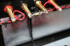
We take pride of good preparation and implementation so I have included an underside photo of the soldering ( my associates handiwork )
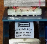
The photo of the side of the Jensen transformer is to show the solder wicking through the board hole properly.
Next update soon - It will be the rest of the components and fitting boards to heat sinks
FR
We have decided to get a start on the PCB boards while we wait for the remainder of the parts to arrive ( some things are just slow to arrive and your itching to start 🙂 )
We haven't put the transistors in yet, as we want to check out some more
heat-sink options for another little mod we saw talk off.
Also note all components are raised 1.5mm above board level.
We take pride of good preparation and implementation so I have included an underside photo of the soldering ( my associates handiwork )
The photo of the side of the Jensen transformer is to show the solder wicking through the board hole properly.
Next update soon - It will be the rest of the components and fitting boards to heat sinks
FR
Attachments

Last edited:
I have one of those chassis with the "Sepaker" posts!
I know I know 😉
You gotta love Chinglish - but hey its at the back and no one sees it unless a photo is posted
FR
The makers of the case must be Pink Floyd fans and listen to -
Another Brick In The Wall
We don't need no education
We don't need no thought control
FR
Another Brick In The Wall
We don't need no education
We don't need no thought control
FR
We have also decided to remove the soft start section and replace it with a resistor
I don't understand this. Could you please explain the usage of a resistor instead of a soft start section?
Thanks!
- Status
- Not open for further replies.
- Home
- Amplifiers
- Pass Labs
- Upgrade F5 to F6