You will need to keep a close eye on the dissipation in that LND150, but it will work. I stuck several different mosfets into my test board and most of them worked. This is the actual circuit I used.Looking forward to see what you end up putting together zintolo after all the study and simulations. I wish I had your patience.
I currently have a couple SS driver stages to build that I want to try with the UNSET output stage. It will be a bit though as I have decided my 26HU5 UNSET really deserves a case worthy of moving into the living room. That along with some new speakers and finishing some other projects that have been sitting around partially assembled before I get back to playing with the other UNSET board.
Hey George. I just re-read your post #500 in this thread. Are you saying I can just stick a LND150 in place of the driver tube in the UNSET with the CCS mod and it will work? I have a few of those sitting in my parts bin.
I pushed the IXTP6N100D2 to nearly 85 watts and it did not blow. The case temp was far too high at over 90C. I asked people in the Pass Labs forum how hard they pushed a TO-247 case mosfet and the recommendations ranged from 40 to 55 watts with a heat sink that does not exceed 55C.@Tubelab_com what is the maximum dissipated power you would suggest for the top mosfet?
l.
Attachments
Thanks @Tubelab_com !
Have you tried to have two IXTP6N100D2 in parallel? Something like:
Toroidy’s 600 Ohm transformer is declared for 60 Wrms (too optimistic?) and it would be interesting to go above 25 Wrms.
Have you tried to have two IXTP6N100D2 in parallel? Something like:
- both drains directly on the primary of the output transformer;
- both sources to the source of the same pmosfet (not to affect the slewrate of the deiver) through a 0.1 Ohm resistor (each) to measure the current of each IXTP6N100D2;
- each gate on individual voltage dividers to set gain and bias.
Toroidy’s 600 Ohm transformer is declared for 60 Wrms (too optimistic?) and it would be interesting to go above 25 Wrms.
Of course same question may be applied to smaller tubes in parallel with 1 Ohm from each cathode to the source of the pmosfet.
To protect the pmosfet, can we use a resistor and a zener to ground?
So that if the voltage goes above the (or a series of) zener voltage (200V?), the resistor will limit the swing and will keep it below 250V.
During normal operation the zener should not affect the load of the driver (will it in a way I can't see?).
Thanks
Roberto
I had two of the output fets in parallel with no success, one wound up hogging all the current, and it wasn't always the same part that got hot. If one fet gets warm faster it draws more current leading to more heat and runaway. I did not try two separate feedback paths. Each gate had its own ferrite / resistor stopper and the source resistors were 1 ohm. A 10 ohm might help though. These experiments got me 4 dead mosfets, so I abandoned the idea for now.Thanks @Tubelab_com !
Have you tried to have two IXTP6N100D2 in parallel?
Toroidy’s 600 Ohm transformer is declared for 60 Wrms (too optimistic?) and it would be interesting to go above 25 Wrms.
My experience with other Toroidy transformers show that the 60 watt number is a bit optimistic. The 1500 ohm KT88PSE's can do 25 to 30 watts at 40 Hz when driven by a pair of 26HU5's in UNSET mode. More power brings saturation. I did see 40 clean watts at 40 Hz out of the 600 ohm Toroidys with the FETSET, but did not go further due too heat issues,.
I'll probably build a FETSET of about 20 to 25 watts using the circuit I posted. If I want to go bigger I'll use a similar circuit to make huge amounts of drive VOLTAGE to feed a source follower with a modulated drain supply (class H) for efficiency improvement like I did with vacuum tubes in the old Circuit Cellar magazine article.
If a tube arc or a shorted output fet happens a resistor and zener will not help. All of the stored energy in the power supply caps plus the supply's output will hit the lower fet. A fuse in it's drain might keep it from exploding, but then the fuse might explode. Wimpy power supplies tend to make wimpy sound, so there are tradeoffs that need to be made.

@Tubelab_com
I'm thinking about the resistor and zener at the gate of the pmosfet, to avoid to exceed the 250V it can handle.
I'm thinking about the resistor and zener at the gate of the pmosfet, to avoid to exceed the 250V it can handle.
I think that there are one or two UNSET Beta boards left, and I do not plan on ordering any more boards unless there is a valid reason. There are at least 10 of the UNSET Power Head (output stage only) boards seen in posts #445 through 459. Those have proven the UNSET concept by pushing the audio power meter to 525 watts from 4 X 26HU5 tubes in a push pull amp using the UD boards to drive them. See posts #453 and #458. I do plan to continue developing the UNSET design as time permits.
I can sell some, but not all of the Power Head boards if they are useful to someone.
I will be away from my lab for 7 to 10 days starting early tomorrow morning. I can check the stock more accurately when I return.
I can sell some, but not all of the Power Head boards if they are useful to someone.
I will be away from my lab for 7 to 10 days starting early tomorrow morning. I can check the stock more accurately when I return.
I write here just to suggest to try two very efficient internal feedback I've tried, and not yet seen here.
Split the driver plate resistor in two resistors, then feedback/bootstrap through a resistor (better two in series) from the primary of the output transformer to the point in the middle of the two resistor loads of the driver, in order to minimize the ac voltage across the lower resistor of the driver.
This way you'll have a poor man CCS load for the driver, with more gain and incredibly low distortions.
This at the expense of a Zout increase.
Another bootstrap technique that can be applied is through a 10uF capacitor from the cathode of the output tube to the central point of the split driver plate resistors.
Again this will create a poor man (a bit richer than the previous one) CCS load for the driver, with some limits due to the RC cutoff, but with more linearity and way lower Zout degradation.
I experimented with the two resistors in series feeding the plate of the driver tube thing several years ago. Some driver tubes like it, some don't.
There was an article in one of the audio magazines some time ago, where the feedback was derived from the UL tap on the OPT. Never tried it with any decent OPT's though. I have used some low buck guitar amp OPT's in most of my push pull amps with good results, but they don't have UL taps. The article was probably in Glass Audio and it might have been called an E-Linear circuit, but my aging brain tends to get old memories about half right.
In this case one can use positive feedback for a CCS like bootstrapping effect. McIntosh used this to get high drive voltages. In this case a triode driver with a lowish plate resistance is needed.
One can also use negative feedback for distortion reduction. Negative feedback can be applied through the plate load, or to the screen grid in the case of a pentode driver.
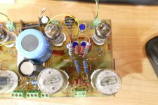
This old push pull board was my first use of UNSET technology though it is not SET. Note the flying resistors and populated resistors where just about every possible feedback configuration was tried. The driver is a 6JD6 pentode and the output tubes are 6GF5 sweep tubes which are shrunken 6DQ6's. Power is 80 WPC from a regulated 500 volt supply or 50 to 60 WPC from an Antek power transformer whose voltage drops when the amp is driven hard.
There was an article in one of the audio magazines some time ago, where the feedback was derived from the UL tap on the OPT. Never tried it with any decent OPT's though. I have used some low buck guitar amp OPT's in most of my push pull amps with good results, but they don't have UL taps. The article was probably in Glass Audio and it might have been called an E-Linear circuit, but my aging brain tends to get old memories about half right.
In this case one can use positive feedback for a CCS like bootstrapping effect. McIntosh used this to get high drive voltages. In this case a triode driver with a lowish plate resistance is needed.
One can also use negative feedback for distortion reduction. Negative feedback can be applied through the plate load, or to the screen grid in the case of a pentode driver.
This old push pull board was my first use of UNSET technology though it is not SET. Note the flying resistors and populated resistors where just about every possible feedback configuration was tried. The driver is a 6JD6 pentode and the output tubes are 6GF5 sweep tubes which are shrunken 6DQ6's. Power is 80 WPC from a regulated 500 volt supply or 50 to 60 WPC from an Antek power transformer whose voltage drops when the amp is driven hard.
Attachments
Last edited:
The circuit you are describing is called E-linear and taken from AudioXpress magazine, April 2005.
http://www.pmillett.com/elinear.htm
It's a negative feedback circuit that triodifies the output tube curves.
My idea is to use positive feedback from output tube plate to driver plate to have the same ac swing on the top and bottom of one of the two driver plate resistors, so transforming it in a CCS.
Same applies with the capacitor from the cathode of the output tube.
Thanks for your feedback @Tubelab_com !
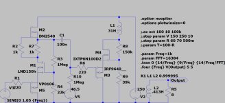
I'm now working on LTSPICE with a UNSET pentode driver and results are even better (resumed bottom right of the image):


I have used it with a 12AT7 indeed, and results are really good soundwise (no measurements done).In this case one can use positive feedback for a CCS like bootstrapping effect. McIntosh used this to get high drive voltages. In this case a triode driver with a lowish plate resistance is needed.
I'm now working on LTSPICE with a UNSET pentode driver and results are even better (resumed bottom right of the image):
Using positive feedback to match the ac swing on both sides of R3, the distortion is greatly reduced as well because the driver runs on a flat loadline.One can also use negative feedback for distortion reduction. Negative feedback can be applied through the plate load, or to the screen grid in the case of a pentode driver.
Last edited:
Most likely a bombWhat could this be?
I lit the fuse and it blew out 50 watts.Most likely a bomb
Yes, they are metal 6L6s that are probably older than I am. I slapped them into a test amp that already had KT88's in it to verify that they were good. All five tubes worked. They will be used in a guitar amp design where no semiconductors are present. The only active devices will be old metal tubes, since I have collected a box full. I'm looking for a modern high gain design that could have been made before I was born.
Experiments with the usual audio output tubes in the UNSET board reveal that power output is limited to about what you would get by triode wiring the same tube, maybe 10 to 20% more. I decided to force pentode operation by sticking a cap from the control grid to ground which eliminates the "Schade" feedback while leaving the DC level unchanged. I was getting 30 watts at about 1.5% THD in normal UNSET mode. That changed to 50 watts at 2 to 2.7% THD with the shunt cap, depending on which pair of tubes I used.
There are likely several possibilities here depending on the goals of a particular build. More experiments are needed.
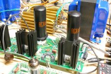
I have been tinkering with lots of different tubes, and yes some have plate caps. That board has seen everything from 6V6GTs to 6LW6s and 26HU5s. I just leave the plate caps hanging when testing capless tubes. I have the boards mounted such that I can change the jumpers so that I can run any octal tube I want. It is currently wired for the common audio tubes like the 6L6GC, KT88 and others. There are three different size plate caps commonly seen on TV sweep (line output) tubes, so I need to change them for some swaps.
There are three TV sweep tubes from the 1950's that have a pinout compatible with the typical audio output octals. They are the 6BQ6, the 6CU6, and the 6DQ6. Some were found in three physical sizes, the G, GT, and GA varieties. They were the most common tube found in the trash dump where I shopped for amplifier parts as a kid in the early 60s. 6V6s were not too common in the trash, but there were lots of discarded old TV sets. Many of my early DIY guitar amps used a 6BQ6GT or GA for the output tube. I still have plenty of all three and tested them in the UNSET board. All work great in push pull, but aren't very linear in SE.
By connecting a "small" plate cap to pin 3 of the tube socket any of them will be pin compatible with a typical audio tube. They are NOT electrically compatible and bad stuff can happen if they are installed without circuit changes, primarily screen grid voltage. I fried a few parts as a kid trying to learn this. The UNSET test setup that you see has different adjustable lab power supplies for every power source. I have been testing push pull stuff with my Universal Driver Boards feeding UNSET power head (output stage only) boards. I still keep thinking about building a 1 KW (500WPC) tube amp just because I can, but I have no use for. I have all the parts, but also have several more useful projects to build first. I think I'll do a couple guitar amps first since I only have one that works, and I have too many HiFi amps. I have never heard an UNSET guitar amp either.
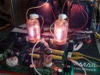
This is what happens when you just plug a pair into an SSE board that runs on 450 volts or so. When Antique Electronics Supply and a couple other vendors decided to sell off most of their NOS tubes many years ago (2007 to 2009) I bought a lot of "NOS" TV sweep tubes, cheap. Some were not new at all and were actually crusty old tubes stuffed back into a non matching box. I stuck an ugly pair into an SSE and cranked them up in a test to see just how much power they would make. I can't remember exactly, but it was well over 20 watts for about 10 minutes.
There are three TV sweep tubes from the 1950's that have a pinout compatible with the typical audio output octals. They are the 6BQ6, the 6CU6, and the 6DQ6. Some were found in three physical sizes, the G, GT, and GA varieties. They were the most common tube found in the trash dump where I shopped for amplifier parts as a kid in the early 60s. 6V6s were not too common in the trash, but there were lots of discarded old TV sets. Many of my early DIY guitar amps used a 6BQ6GT or GA for the output tube. I still have plenty of all three and tested them in the UNSET board. All work great in push pull, but aren't very linear in SE.
By connecting a "small" plate cap to pin 3 of the tube socket any of them will be pin compatible with a typical audio tube. They are NOT electrically compatible and bad stuff can happen if they are installed without circuit changes, primarily screen grid voltage. I fried a few parts as a kid trying to learn this. The UNSET test setup that you see has different adjustable lab power supplies for every power source. I have been testing push pull stuff with my Universal Driver Boards feeding UNSET power head (output stage only) boards. I still keep thinking about building a 1 KW (500WPC) tube amp just because I can, but I have no use for. I have all the parts, but also have several more useful projects to build first. I think I'll do a couple guitar amps first since I only have one that works, and I have too many HiFi amps. I have never heard an UNSET guitar amp either.
This is what happens when you just plug a pair into an SSE board that runs on 450 volts or so. When Antique Electronics Supply and a couple other vendors decided to sell off most of their NOS tubes many years ago (2007 to 2009) I bought a lot of "NOS" TV sweep tubes, cheap. Some were not new at all and were actually crusty old tubes stuffed back into a non matching box. I stuck an ugly pair into an SSE and cranked them up in a test to see just how much power they would make. I can't remember exactly, but it was well over 20 watts for about 10 minutes.
Attachments
Hi George, which usual audio tubes have you tested, and why do you think they have this limited amount of power?Experiments with the usual audio output tubes in the UNSET board reveal that power output is limited to about what you would get by triode wiring the same tube, maybe 10 to 20% more.
- Home
- More Vendors...
- Tubelab
- UNSET Beta Board Build