I suppose it is a simple question, but I haven't been able to find the answer.
When designing an unregulated power supply, how do we determine if the output impedance is low enough? Less than half the input impedance of the total load?
And do we include the transformer's secondary resistance in the determination of output impedance?
Thanks.")
When designing an unregulated power supply, how do we determine if the output impedance is low enough? Less than half the input impedance of the total load?
And do we include the transformer's secondary resistance in the determination of output impedance?
Thanks.
Is it a Ac to Dc supply using a bridge rectifier and caps? If so, the output impedance is the same as the cap impedance, until the charge pulse happens, then the transformer impedance becomes part of the equation but it gets complicated. The cap impedance is a good approximation. And the output impedance should be closer to 1/10 (idealy as low as possible) of the load.
Yes I meant an AC to DC supply, basically Transformer -> Rectifier -> Passive filters (RC/LC) kind of power supply.
I suppose for mid to high frequency, the cap's ESR is a good approximation. But for low frequencies where the current draw is beyond what the caps can store, the output impedance became the DC resistance of all components in series?
I suppose for mid to high frequency, the cap's ESR is a good approximation. But for low frequencies where the current draw is beyond what the caps can store, the output impedance became the DC resistance of all components in series?
No, it then becomes a sampled system, where the sample frequency is 100 or 120Hz, depending where you live.But for low frequencies where the current draw is beyond what the caps can store, the output impedance became the DC resistance of all components in series?
Basically, it will obey the rules of sampled systems, ie. the transformer's impedance and upstream impedances will be multiplied by the ratio of the sampling period to the aperture time, but with some quirks: the average aperture time isn't constant and depends on the load, and the sampling itself is not purely binary, it is in fact a multiplication by a complex function, also varying with the load.
And because it is a discrete time system, funny things will happen when the stimulus frequency is a multiple or submultiple of the sampling frequency.
Unless you are familiar with Z-transform and similar tools, your best bet is to use very large filter caps...
For AC it is 1/2pi.f.C, with f in Hz and C in Farad.I suppose it is a simple question, but I haven't been able to find the answer.
When designing an unregulated power supply, how do we determine if the output impedance is low enough? Less than half the input impedance of the total load?
And do we include the transformer's secondary resistance in the determination of output impedance?
Thanks.
For DC derived from 60Hz with full wave rectifier is 15.10 power -3/C. C is the Recervoir value in Earad.
Unless you are familiar with Z-transform and similar tools, your best bet is to use very large filter caps...
Meaning, the 1:10 impedance ratio can not be practically achieved? And, how large is "very large"? I suppose there is some kind of rules of thumb with respect to average current draw?
Are you asking about AC impedance or DC impedance? AC impedance is roughly given by the last cap in the supply. DC impedance (i.e. how much does it droop under load) is given by a messy combination of transformer secondary effective resistance (multiplied by charging pulse duty cycle) and storage capacitor value.
Effective secondary resistance R's = Rs + Rp x (Vs/Vp)^2
For 50Hz supply and fullwave rectification the reservoir caps get recharged every 10ms. They then droop under load by roughly I x 0.01/C, but the average DC droop will be half this so effective DC resistance due to the reservoir cap is 0.005/C (e.g. 5 ohms for 1000uF).
You need to know/measure/guess the charging duty cycle, otherwise use a factor of 5. Then add on any DC resistance from RC smoothing or choke resistance.
So Rpsu = 5 R's + 0.005/C + Rdc
This is only a rough estimate, but it will tell you whether you are close or way off the mark.
For AC it is 1/2pi.f.C, with f in Hz and C in Farad.
For DC derived from 60Hz with full wave rectifier is 15.10 power -3/C. C is the Recervoir value in Earad.
Thanks.
How about DC derived from 50Hz supply?
Are you asking about AC impedance or DC impedance? AC impedance is roughly given by the last cap in the supply. DC impedance (i.e. how much does it droop under load) is given by a messy combination of transformer secondary effective resistance (multiplied by charging pulse duty cycle) and storage capacitor value.
Effective secondary resistance R's = Rs + Rp x (Vs/Vp)^2
For 50Hz supply and fullwave rectification the reservoir caps get recharged every 10ms. They then droop under load by roughly I x 0.01/C, but the average DC droop will be half this so effective DC resistance due to the reservoir cap is 0.005/C (e.g. 5 ohms for 1000uF).
You need to know/measure/guess the charging duty cycle, otherwise use a factor of 5. Then add on any DC resistance from RC smoothing or choke resistance.
So Rpsu = 5 R's + 0.005/C + Rdc
This is only a rough estimate, but it will tell you whether you are close or way off the mark.
Thanks a lot. Let me chew on that for a while, I have a feeling that I haven't done asking.
Are you asking about AC impedance or DC impedance?
Which one of these do I have to meet the 1:10 source to load ratio? Both?
For 50Hz supply and fullwave rectification the reservoir caps get recharged every 10ms. They then droop under load by roughly I x 0.01/C, but the average DC droop will be half this so effective DC resistance due to the reservoir cap is 0.005/C (e.g. 5 ohms for 1000uF).
Sorry I don't quite under stand this part. SO do I get 10 ohms for 2000uF?
Thanks again.
Thanks.
For the size power supply cap, here it talks about a rule of thumb of about 1000uF per 1A of current output. Is that a good number?
Solid State Power Amplifier Supply Part 2
For the size power supply cap, here it talks about a rule of thumb of about 1000uF per 1A of current output. Is that a good number?
Solid State Power Amplifier Supply Part 2
Last edited:
Thanks.
For the size power supply cap, here it talks about a rule of thumb of about 1000uF per 1A of current output. Is that a good number?
Solid State Power Amplifier Supply Part 2
yes.....i have lots of caps so i use them on my tube amps as welll....
Which one of these do I have to meet the 1:10 source to load ratio? Both?
Sorry I don't quite under stand this part. SO do I get 10 ohms for 2000uF?
Thanks again.
I think we should realize that although we talk about a DC power supply, the load from an audio device is an AC load.
The Zout of a simple rectifier + cap is the impedance of the cap at the freq of the load signal. The formula has been given before and it is of course dependent on the freq of the signal you are amplifying. Meaning the Zout is highest at low freqs. So you probably want to size the cap for say 1/10 of an 8 ohms load at 20Hz. Just plug the numbers in the formula C=1/(2.pi.f.(0.8 ohms)).
Don't worry about DC Zout - it's pretty irrelevant for audio in this context.
jan didden
Last edited:
Don't worry about DC Zout - it's pretty irrelevant for audio in this context.
Thanks Jan.
So, we can completely ignore it? In my case, my transformer's secondary DC resistance is 220 ohms, and my DC load is under 1k ohms. If I plug the numbers into the formula I can't even hit 1:1 ratio let alone 1:10.
^what your figure means is that you will have bigger voltage drop with your load connected....
as long as you have your operating points achieved regardless you should be fine.....
it is not just secondary dc resistance of your traffo.....the primary dc resistance has an effect also.....
the kind of dc resistances you have is indicative of tube type psu's...
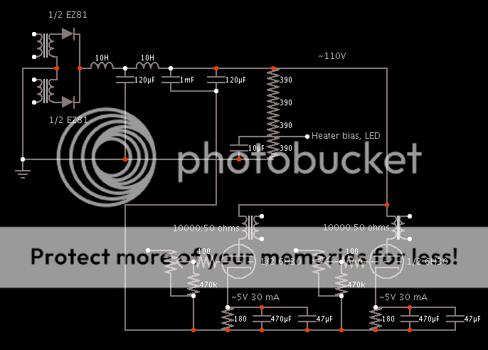
what are you building anyway? post some schematics and we will be able to help you for sure....
as long as you have your operating points achieved regardless you should be fine.....
it is not just secondary dc resistance of your traffo.....the primary dc resistance has an effect also.....
the kind of dc resistances you have is indicative of tube type psu's...
what are you building anyway? post some schematics and we will be able to help you for sure....
aha....just as i suspected.....
what are the dc resistances of your chokes?
110v at 30mA is a 3.7k load
your total load is 70mA......this is in series with your chokes so you have to consider that also...
you want to know what your raw secondary ac is? right?
Thanks again.
The power transformer is rated at 230V, when loaded it is around 200V. Secondary windings DC resistance is 220 ohms per winding.
Chokes' DC resistance is 90 ohms for both.
The chain of 390 ohms resistors, it draws about another 70mA.
If you wonder why the resistor chain is wasting so much current, I did this to cut down the supply voltage. If you wonder why I didn't cut voltage the usual way (putting them in series with the chokes), I observed a noticeable improvement in bass when comparing between the 2. I thought it interesting, and this made me look into the effect of Zout of PSU. But this also keep the load DC resistance low, so I plan to get rid of it.
Of course in theory I should just dump the power transformer, replace it with one with appropriate rating, and do without the resistors. but that cost money.
So total current draw is around 140mA, at 110V, it would be about 786 ohms overall.
- Status
- This old topic is closed. If you want to reopen this topic, contact a moderator using the "Report Post" button.
- Home
- Amplifiers
- Power Supplies
- Unregulated power supply output impedance