pretty much yup
you can mount lazy fan in front of heatsink , just to keep thingie stubbornly cool

first several attempts do not write result down , just observe behavior of DUT ....... if you find kink in reading that's good
it's worst , when matching , to have constantly changing readout
can't help more , never did matching of these made of preputium parts
several I have , got already matched ..... either by some clever Greedy Boy , or Ubergreedy One , himself .

you can mount lazy fan in front of heatsink , just to keep thingie stubbornly cool

first several attempts do not write result down , just observe behavior of DUT ....... if you find kink in reading that's good
it's worst , when matching , to have constantly changing readout
can't help more , never did matching of these made of preputium parts
several I have , got already matched ..... either by some clever Greedy Boy , or Ubergreedy One , himself .
Last edited:
pretty much yup
you can mount lazy fan in front of heatsink , just to keep thingie stubbornly cool
first several attempts do not write result down , just observe behavior of DUT ....... if you find kink in reading that's good
it's worst , when matching , to have constantly changing readout
can't help more , never did matching of these made of preputium parts
several I have , got already matched ..... either by some clever Greedy Boy , or Ubergreedy One , himself .

Thanks ZM
Kind of nerve racking doing this, for me anyway. I could never be a Doctor!
So far my test bed looks like it works. Only thing is the pot is backwards for the 2SJ28.
If I’m doing this correctly my first four 2SJ28’s measured 6.13, 12.73, 10.53, 8.85. Pretty wide range.
Unless I have something wrong. After a minute or two, with both power supplies on, the back of the VFET is fairly warm but not too hot to touch.
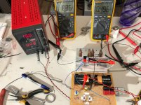
I finished measuring the 2SJ28’s. But I have something wrong in my test rig. Not acting the same when trying to test the 2SK82’s.
It’s acting like I have the battery and power supply feeds reversed. Can someone read the schematic I posted and double check? On the 2SJ28’s I applied battery power, then turned on the power supply and the meter reading VGS would start showing voltage. On the 2SK82’s I show voltage on the meter reading VGS as soon as I switch on the battery.
But after testing the 26 pcs of 2SJ28’s I’m done for the day anyway.
Here are the readings
2SJ28
12.87
12.79
12.66
12.61
12.58
12.43
12.39
12.37
12.18
11.97
11.96
11.81
11.79
11.60
11.53
11.39
11.34
11.14
11.05
11.02
11.01
10.59
10.39
8.85
6.13
One is at 12.97 @0.77v min on pot
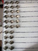

I know I’m kinda late to VFET amp building. But since I want to build a bigger amp, have 26 pairs, and will need to measure, swap, or hopefully be able to buy more to meet my goal of 16 matched pairs, I want to share how I measured mine for reference.
I had a memory issue and a bad pot to make it more complicated when I switched over to measuring the 2SK82’s. So this time I wrote out each step, what happens, so in the future I’ll realize earlier if I have a bad part.
Attach VFET to heat sink. Make sure pins are clear of aluminum.
Clip “G” lead to “G” pin
Clip “S” lead to “S” pin
Clip “+” lead from meter A to “S” pin
Clip “-“ lead from meter A to “G” pin
Clip “+” lead from meter B to power supply side of the 1Ohm resistor
Clip “-“ lead from meter B to “D” side of 1Ohm resistor
Make sure 10K pot is turned all the way CCW
Connect the twin 9v battery pack to circuit, switch or clip leads.
As soon as you connect the battery pack to the circuit, meter A will read voltage, in my case it was about 12.45v
Nothing is yet showing on meter B
Turn on 19v power supply
Nothing changed on either meter for me at this point except one 2SJ28 that I think is way off spec.
Then slowly start turning pot CW. Depending on the VFET you might turn the pot 1/4 turn before either meter registers a change.
Watch meter B as turning to get to 0.50v. I let mine “test” about a minute to warm up and stabilize. The voltage showing on meter A will be the VGA.
Reverse each step, in order, to stop the test. Double check that both power supplies are off and pot is all the way CCW before unclipping leads.
As an aside, I noticed that having my soldering station active on the same house circuit during testing would affect the results by 0.01-0.03, even though the power supply and meters read the same.
Here are the results of the 2SK82 tests;
10.14
9.78
9.62
9.61
9.26
9.24
9.10
8.95
8.77
8.61
8.48
8.34
8.29
8.28
8.08
8.03
8.01
7.93
7.86
7.78
7.73
7.66
7.65
7.57
7.36
7.31
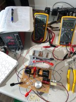
All lined up waiting to play!
I had a memory issue and a bad pot to make it more complicated when I switched over to measuring the 2SK82’s. So this time I wrote out each step, what happens, so in the future I’ll realize earlier if I have a bad part.
Attach VFET to heat sink. Make sure pins are clear of aluminum.
Clip “G” lead to “G” pin
Clip “S” lead to “S” pin
Clip “+” lead from meter A to “S” pin
Clip “-“ lead from meter A to “G” pin
Clip “+” lead from meter B to power supply side of the 1Ohm resistor
Clip “-“ lead from meter B to “D” side of 1Ohm resistor
Make sure 10K pot is turned all the way CCW
Connect the twin 9v battery pack to circuit, switch or clip leads.
As soon as you connect the battery pack to the circuit, meter A will read voltage, in my case it was about 12.45v
Nothing is yet showing on meter B
Turn on 19v power supply
Nothing changed on either meter for me at this point except one 2SJ28 that I think is way off spec.
Then slowly start turning pot CW. Depending on the VFET you might turn the pot 1/4 turn before either meter registers a change.
Watch meter B as turning to get to 0.50v. I let mine “test” about a minute to warm up and stabilize. The voltage showing on meter A will be the VGA.
Reverse each step, in order, to stop the test. Double check that both power supplies are off and pot is all the way CCW before unclipping leads.
As an aside, I noticed that having my soldering station active on the same house circuit during testing would affect the results by 0.01-0.03, even though the power supply and meters read the same.
Here are the results of the 2SK82 tests;
10.14
9.78
9.62
9.61
9.26
9.24
9.10
8.95
8.77
8.61
8.48
8.34
8.29
8.28
8.08
8.03
8.01
7.93
7.86
7.78
7.73
7.66
7.65
7.57
7.36
7.31

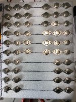
All lined up waiting to play!

Last edited:
Like Walter I want to build a very special amplifier.
And with no intention of trying to one-up Walters special amplifier project, I want to build a similar set of mono blocks.
My first, and still best speaker project was a set of Troel Gravesen’s Ekta Grande. I built the cabinets similar to the Sony SS-AR1’s and Troel’s design was a similar approach. The drivers in both speakers are ScanSpeak, and the midrange drivers are the same, mine are just the next size smaller. Both speakers have 4 Ohm loads, the Ekta’s below;
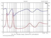
Unbeknown to me at the time I was building my speakers, a local Audio Store actually had a set of the Sony’s in stock. Through a mixup in business cards, work related, I ended on the phone with the owner of the store talking audio. Long story short he asked me to bring my speakers over for a shootout of sorts. We have been great friends since, BTW.

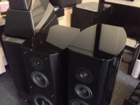
So with a bunch$$$ of Mark Levinson gear (ML53 amps, ML 326S pre, and ML390S player) and all reference Transparent Cables (speaker cables alone retailed for $38k) we listened to music and compared my build to the Sony’s and a pair of Wilson Alexia’s (I think that’s the right model). Of course the Sony’s beat me, but by a very small margin. Especially when you consider the price/cost difference. But I would say similar sound. The Sony’s also benefitted from the next size larger drivers for the midrange and mid woofers. The Wilsons were a pretty big step up from both the Sony’s and mine.
So after reading about the Pass amp project for Sony and the AR1’s I was really interested in building something if I could ever get the VFETs. So now I have measured the 26 pairs that I have and below is what my simple mind would like to build. So don’t laugh to hard at my ignorance, but below is what I think I want to build. The VFET’s I have didn’t match up as well as what I have read they need to for something like this. But I have to start somewhere to start the dialogue. Maybe someone has some to swap for the 10 pairs I have left over or some I could buy? Maybe suggestions on better placement?
Red is one amp, green is the other. Another probably stupid question, but since the matching is not so good, could the voltage be adjusted side to side via a trimmer to better match VGS?
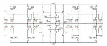
I measured all at 19v, 0.5v over the 1 Ohm resistor as per the Pass drawing. These are the ones not mentioned in the drawing
2SK82 10.14, 9.78, 9.10, 8.95, 8.77, 8.61, 8.48, 8.34, 8.08, 7.57
2SJ28 12.97, 12.79, 12.66, 12.43, 12.18, 10.59, 10,39, 8.85, 6.13, one measures 12.97 at 0.77v min pot.
And with no intention of trying to one-up Walters special amplifier project, I want to build a similar set of mono blocks.
My first, and still best speaker project was a set of Troel Gravesen’s Ekta Grande. I built the cabinets similar to the Sony SS-AR1’s and Troel’s design was a similar approach. The drivers in both speakers are ScanSpeak, and the midrange drivers are the same, mine are just the next size smaller. Both speakers have 4 Ohm loads, the Ekta’s below;

Unbeknown to me at the time I was building my speakers, a local Audio Store actually had a set of the Sony’s in stock. Through a mixup in business cards, work related, I ended on the phone with the owner of the store talking audio. Long story short he asked me to bring my speakers over for a shootout of sorts. We have been great friends since, BTW.


So with a bunch$$$ of Mark Levinson gear (ML53 amps, ML 326S pre, and ML390S player) and all reference Transparent Cables (speaker cables alone retailed for $38k) we listened to music and compared my build to the Sony’s and a pair of Wilson Alexia’s (I think that’s the right model). Of course the Sony’s beat me, but by a very small margin. Especially when you consider the price/cost difference. But I would say similar sound. The Sony’s also benefitted from the next size larger drivers for the midrange and mid woofers. The Wilsons were a pretty big step up from both the Sony’s and mine.
So after reading about the Pass amp project for Sony and the AR1’s I was really interested in building something if I could ever get the VFETs. So now I have measured the 26 pairs that I have and below is what my simple mind would like to build. So don’t laugh to hard at my ignorance, but below is what I think I want to build. The VFET’s I have didn’t match up as well as what I have read they need to for something like this. But I have to start somewhere to start the dialogue. Maybe someone has some to swap for the 10 pairs I have left over or some I could buy? Maybe suggestions on better placement?
Red is one amp, green is the other. Another probably stupid question, but since the matching is not so good, could the voltage be adjusted side to side via a trimmer to better match VGS?

I measured all at 19v, 0.5v over the 1 Ohm resistor as per the Pass drawing. These are the ones not mentioned in the drawing
2SK82 10.14, 9.78, 9.10, 8.95, 8.77, 8.61, 8.48, 8.34, 8.08, 7.57
2SJ28 12.97, 12.79, 12.66, 12.43, 12.18, 10.59, 10,39, 8.85, 6.13, one measures 12.97 at 0.77v min pot.
I would go with it ;
maybe first step , to build fast mockup of just (one side, SE) OS, with 0R1 (or even 0R05) inserted in each source , then bang it with some voltage , loaded with 8R and observe what's reading across each source resistor
feel free to do it slowly , increasing building enjoyment .........
maybe first step , to build fast mockup of just (one side, SE) OS, with 0R1 (or even 0R05) inserted in each source , then bang it with some voltage , loaded with 8R and observe what's reading across each source resistor
feel free to do it slowly , increasing building enjoyment .........
I would go with it ;
maybe first step , to build fast mockup of just (one side, SE) OS, with 0R1 (or even 0R05) inserted in each source , then bang it with some voltage , loaded with 8R and observe what's reading across each source resistor
feel free to do it slowly , increasing building enjoyment .........
ZM, thanks much for the reply!
I need a project to think and dream about once I have the current project under construction. But I think of new projects faster than I have time to build!
This weekend I will be installing the Babelfish J amps into my console and hopefully start playing with testing. The second life F5Tv3’s are underway. I wrapped up the steering issues on my modified ‘69 Mercedes this past weekend and part of the next two weekends will be spending time stripping the exterior of all parts and trim to go to the paint shop on the 4th.
After your previous comments about my projects being “overkill” I ordered a vanity plate for the MB “OHVRKL”. DMV here take 60-90 days to produce. Thanks.
But back to this project, yes will take some time to get going. If the general consensus is that I can make the amp work with the VFETs I have, I can start trying to figure out the power supply, the chassis, and help with designing the amp. Give my brain some exercise.
VFET measure, exchange
While I’m still in the pre-build stage of my VFET project I thought I would try to get closer matches and maybe help other members too.
Since I have a test platform setup I can measure for members that may not.
I can offer to measure and maybe help others figure out what they have and maybe help each other out by swapping for better matches.
PM me if interested, I’ll pay return shipping even if we can’t help each other out.
I have already helped another member in this way.
- Status
- This old topic is closed. If you want to reopen this topic, contact a moderator using the "Report Post" button.
- Home
- Amplifiers
- Pass Labs
- Unobtainium, what to do with them?
