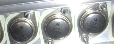
The "manufacture" should be Motorola, well, the logo is there.
After a search on google, the only webpage that I see was:
http://www.mailameal.com/dyn/d2002.66946.motorola.power.devices.aluminum.heatsink.cms
...but where is the information about this "guys"?? I don´t no...weird
After a search on google, the only webpage that I see was:
http://www.mailameal.com/dyn/d2002.66946.motorola.power.devices.aluminum.heatsink.cms
...but where is the information about this "guys"?? I don´t no...weird
And the front.
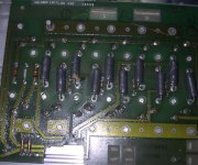
I'm thinking they were used in a high current capacity because of the low ohm resistors and thick traces but it could be an rf module?
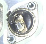
I popped the top off one just to see the die size and connecting wires, as if this means anything, well maybe die size means something. The pic is are in the next post.
I'm thinking they were used in a high current capacity because of the low ohm resistors and thick traces but it could be an rf module?
I popped the top off one just to see the die size and connecting wires, as if this means anything, well maybe die size means something. The pic is are in the next post.
It sure looks like an audio output stage from something, especially if it has the low resistance ballast resistors.
Those are indeed Moto xstrs, adn that is a date code, but thbe other number is just a house number. It would have been the part number that whoever made the unit used. They order the parts stamped with theit number for use in house. If you contacted Moto witht the number and describe it as a TO3, they might tell you what it was under the skin, but that is proprietaru information. They would knly tell you if the OEM whose number it was was no longer in operation or if the copyrights had expired.
In other words if Marantz contracted Moto to make power xstrs for them, Moto could not reveal to you what they were.
The semi division of Moto is now called On Semiconductors. Moto sold the division off some time ago.
Current popular audio output stages use Moto MJ15xxx types. The MJ15024/15025 [air are rated for high voltages and high currents. 25 years ago we didn't have parts that big 2N3772 or something was a big deal. So those parts could be anywhere from 40V if they were in some car stereo system up to even 200v. And the current could be anything from not much to 30 amps.
Failing info from Moto, try one in a curve tracer somewhere. The nearest electronics engineering program ought to have one if you don't.
Its power supply stuff, not audio.
I agree with Enzo, they are most likely either 2N3771, 2N3772, or 2N3773 types.
Considering the low, low value of the ballast resistor I would guess they are 2N3771 40V 30A
The bite taken out of the PC board suggests de-milled spares from military stock.
I agree with Enzo, they are most likely either 2N3771, 2N3772, or 2N3773 types.
Considering the low, low value of the ballast resistor I would guess they are 2N3771 40V 30A
The bite taken out of the PC board suggests de-milled spares from military stock.
Any thoughts on testing?
I'm thinking of increasing the vce until the device fails, derate 10 or 15% for a usable vce and then use another for collector current, I'll assume at least 100w dissapation. I'm then left with 10 if they are practical for audio.
I can test for hfe and ft and a few others with out to much trouble, but I don't how to test for maximum Volts and Amps without actually finding them.
Is their a non lethal or more effective method I could use?
Thanks for the help.
You can test Vce with a current source set to 10-100uA. This way you don't destroy the transistor when it breaks down, max Vce is the point where it stops increasing as supply volts increases.
I thought a useful test kit would be a high voltage supply, say 300v, with a switchable current source capable of standing that voltage. Then zeners, transistor vce, MOS vds etc can be measured by reading off the voltage. With a little care in the choice of current, to avoid false readings and yet be non-destructive, it would be useful for checking devices for which there was no data available.")
I thought a useful test kit would be a high voltage supply, say 300v, with a switchable current source capable of standing that voltage. Then zeners, transistor vce, MOS vds etc can be measured by reading off the voltage. With a little care in the choice of current, to avoid false readings and yet be non-destructive, it would be useful for checking devices for which there was no data available.
Too bad, the 2N2357 was 60V/50A/170W.
But probably leaky as hell after a few years.
Hmm..I run out of ideas here. This must be some OEM made device. The heatsinks and layout remind me a bit of old Peavey or Bose gear.
Edit: Not Peavey, Bose yes, maybe even an old Crest...
/Hugo
But probably leaky as hell after a few years.
Hmm..I run out of ideas here. This must be some OEM made device. The heatsinks and layout remind me a bit of old Peavey or Bose gear.
Edit: Not Peavey, Bose yes, maybe even an old Crest...
/Hugo
I did peel back the top of one and it's got a good amount of silicon in there plus dual bonding wires on both the base and emitter terminals.
I decided to use hfe as a means of finding max collector current or at least usuable gain. I then thought maybe I could figure out what it was by plotting is gain curve and matching possibles, but with temperature all over the place and not the best equipment the best I could do is a gain of of 30 at 22A 3V room tempature.
johnnyx, you say setup a couple hundred volt constant current source of 50ua or so and adjust until the transistor vce stops rising with supply, and this will be it's vce or close? Thanks I'll try this.
I don't know where I could get access to a curve tracer or what to do with it if I did.
Thanks for all the help.
Attachments
The part has a HOUSE NUMBER on it. If you are not an expert, you cannot determine its characteristics. Don't waste your time on it. IF you get a little understanding behind you, you can determine whether these devices are NPN or PNP, Ge or Si . I would predict NPN silicon. If so, they can still be used for non critical applications such as a battery charger, etc.
- Status
- This old topic is closed. If you want to reopen this topic, contact a moderator using the "Report Post" button.
- Home
- Amplifiers
- Solid State
- unkown transistor