Yes you can use just half of a 12AX7, no problems !Hi , Yes , I was asking if I could drop the 6av6 stage but later realized that you use it for the feedback loop ..... I got an extra 12ax7 here so I will use half of it in place of the 6av6 .....
Thanx again .....
The feedback is not absolutely necessary but if you remove it (the 39K resistor near the speaker), you will have a more distorsion and a loss in the deep bass because the feedback tends to make the output signal the same as the input one, but you will get twice the gain, just 0,25V RMS at input for full output power ... You can just remove it to hear the difference and try a lower value to get more than 6dB feedback, but not too much like said Mr Natural ...

An externally hosted image should be here but it was not working when we last tested it.
If you like to try to drive 6V6 directly with your tubes preamplifier output, you have to make sure is signal can reach at least 9V RMS ... Maybe you can modify is last stage to bring the feedback loop to this tube but it must have no cathode bypass capacitor and the feedback resistor have to be recalculated for is cathode resistor and the "no feedback" gain ... Also no volume control in between ...
If you like to see if the output of your preamplifier can have 9V RMS output, you can try to hookup a voltmeter to it and pinch the big string to read the voltage., I never try that but I suppose it work, it is probably better to use an analog voltmeter ...
If your preamplifier give enought voltage, you don't need the volume control on the power amp and the C5 input coupling capacitor because there is already one at the output of your preamplifier ... Just plug is output at the junction of grid leakage resistor (R2) and protection resistor (R12). You will also have to replace the voltage dropping resistor R10 in the supply for a 4,3K or 4,7K because the 0,75ma used by the 6AV6 will not be there anymore.
Otherwise, if you use half of the 12AX7 instead of the 6AV6, you can use the other half for something else ... Since you play guitar, a switchable amplitude distorsion stage for example, the 12AX7 are perfect for that, it is done with a too high or too low bias to get a 0V bias clipping or a "cutoff" clipping or both at the same time with a low voltage plate supply ...
Cheers,
Alain.

I mean low plate current, plate voltage is not really involve...Otherwise, if you use half of the 12AX7 instead of the 6AV6, you can use the other half for something else ... Since you play guitar, a switchable amplitude distorsion stage for example, the 12AX7 are perfect for that, it is done with a too high or too low bias to get a 0V bias clipping or a "cutoff" clipping or both at the same time with a low voltage plate supply ...
Look at this excellent tutorial about "triode gain stage" from "valvewizard1" :
http://www.freewebs.com/valvewizard1/Common_Gain_Stage.pdf
They explain very well triode amplifier stage theory and also talk about guitar amplifier ... It is very important to know about "loadlines" to understand how a tube ( or a transistor ) can amplify an input signal.
Happy reading !
Alain.
This is the schematic for my preamp ....
This is the schematic for the preamps .....
It has 2 channels plus relay channel switching then into a LM3886 with an effects loop in between which I would use as the ouput of to go into the 6V6 amp , the whole amp is done with home etched and designed PCB"s (Poweramp PSU ,Preamp PSU ,Realy board , 2 preamps , power amp) .....
Thanx a lot .....
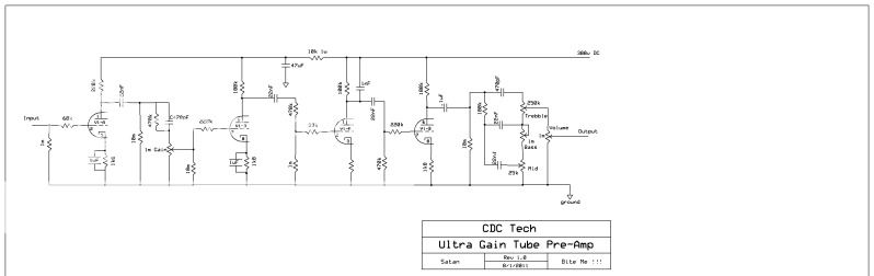
You got a nice tone stack at the end, I like to figure out if it have enough gain to drive the 6V6 directly but I can't read the values of the parts because it is a JPG file, this is good only for photos on Internet ...This is the schematic for my preamp ....
This is the schematic for the preamps .....
It has 2 channels plus relay channel switching then into a LM3886 with an effects loop in between which I would use as the ouput of to go into the 6V6 amp , the whole amp is done with home etched and designed PCB"s (Poweramp PSU ,Preamp PSU ,Realy board , 2 preamps , power amp) .....
Thanx a lot .....
Why don't you save them in PNG format instead, for schematics, it make very small files and very precises. You can open your JPG with a drawing software like "MS Paint", save it in BMP 16 color first to keep only the importants colors and save it again in PNG to reduce the size, I do that with all my schematics ...
I have a good idea to use the other half of your spare 12AX7, you can make a SRPP driver, one triode on top of the other, I will look at that this coming weekend and post the simulation results.
Cheers,
Alain.
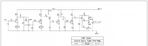
It is small because I think Photobucket resizes them ......
I have uploaded the pic to this site and it seems to be regular size ..... Please excuse my schematic writing abilities , it"s the first schematic I have done on the PC , I usually write them out by hand ....
When you say "one triode on top of the other" do you mean two triodes in paralell ??
I have uploaded the pic to this site and it seems to be regular size ..... Please excuse my schematic writing abilities , it"s the first schematic I have done on the PC , I usually write them out by hand ....
When you say "one triode on top of the other" do you mean two triodes in paralell ??
Attachments
Last edited:
I
When you say "one triode on top of the other" do you mean two triodes in paralell ??
Check out SRPP amplifiers....lots of examples online
The Tube CAD Journal: SRPP Amplifier
Now I can see the parts values ... Thank you !It is small because I think Photobucket resizes them ......
I have uploaded the pic to this site and it seems to be regular size ..... Please excuse my schematic writing abilities , it"s the first schematic I have done on the PC , I usually write them out by hand ....
When you say "one triode on top of the other" do you mean two triodes in paralell ??
Here's a SRPP example I draw for somebody else yesterday :
An externally hosted image should be here but it was not working when we last tested it.
I will include this in my amplifier simulation soon.
Alain.

 ......................
Last edited:
Hi Minion,
Like I tell you not long ago, I draw your preamp schematic in my Spice simulator software and I got the results ...
The good news is yes, you have plenty of gain to drive the 6V6GT or any other power tube in class "A" directly. In fact, there is really too much gain for nothing ... It have a very acceptable distortion too.
The bad news is there is a big lack of treble even at the first 12AX7 stage ...
Here's the preamp schematic :
Normally, a guitar pick-up have a output voltage between 90mV and 1V RMS and you need less than 9V RMS at the 6V6GT grid to get the full power, a minimum gain of about 100 ... But this preamp have a gain of 268700 ... 2687 times too much ... It is completely out of proportion, just two 12AX7 are normally enough ... The distortion is only 1,38% at 8V RMS output but you will get a lot of noises because you use very high values resistors everywhere in that circuit and the gain is very high ...
But don't worry, you will just have to adjust the first volume control (VR1) very very low, almost close ... And if you like distortion in your guitar sound, just adjust it a little higher ... You will have to use the second volume control VR5 as the "normal" volume ...
Here's now the frequency response of your preamp :
Like you can see, the curves drop seriously above 1000 Hz ... It can be good for a bass guitar but not for a lead guitar because you will loss all is sound harmonics, there will be no brightness, to sound will be very "smooth" ...
If you like to modify your preamp to get more treble and less gain and noises, without changing too many thing, just ask me, I already have the schematic ready for the simulator and it will be very easy for me ..
Now the preamp with the 6V6GT power amp together :
You can get the full 4,5W ouput power with just 0,036mV RMS at the input with all volume and tone controls at maximum ... The total distorsion will be 8,226% at full power but much lower at 4W or less.
The only thing you have to change from my last schematic is the voltage dropping resistor R26, 4,3K instead of 3,9K, because there is no more 6AV6 or "half 12AX7". But like I tell you before, you will have to adjust the R34 voltage dropping resistor to get about 285V supply at the output transformer. The 900 ohms value is just for a 332V supply and you will not get that much for sure.
If you have any questions about all that, just ask me.
Cheers,
Alain.
Like I tell you not long ago, I draw your preamp schematic in my Spice simulator software and I got the results ...
The good news is yes, you have plenty of gain to drive the 6V6GT or any other power tube in class "A" directly. In fact, there is really too much gain for nothing ... It have a very acceptable distortion too.
The bad news is there is a big lack of treble even at the first 12AX7 stage ...
Here's the preamp schematic :
An externally hosted image should be here but it was not working when we last tested it.
Normally, a guitar pick-up have a output voltage between 90mV and 1V RMS and you need less than 9V RMS at the 6V6GT grid to get the full power, a minimum gain of about 100 ... But this preamp have a gain of 268700 ... 2687 times too much ... It is completely out of proportion, just two 12AX7 are normally enough ... The distortion is only 1,38% at 8V RMS output but you will get a lot of noises because you use very high values resistors everywhere in that circuit and the gain is very high ...
But don't worry, you will just have to adjust the first volume control (VR1) very very low, almost close ... And if you like distortion in your guitar sound, just adjust it a little higher ... You will have to use the second volume control VR5 as the "normal" volume ...
Here's now the frequency response of your preamp :
An externally hosted image should be here but it was not working when we last tested it.
Like you can see, the curves drop seriously above 1000 Hz ... It can be good for a bass guitar but not for a lead guitar because you will loss all is sound harmonics, there will be no brightness, to sound will be very "smooth" ...
If you like to modify your preamp to get more treble and less gain and noises, without changing too many thing, just ask me, I already have the schematic ready for the simulator and it will be very easy for me ..
Now the preamp with the 6V6GT power amp together :
An externally hosted image should be here but it was not working when we last tested it.
You can get the full 4,5W ouput power with just 0,036mV RMS at the input with all volume and tone controls at maximum ... The total distorsion will be 8,226% at full power but much lower at 4W or less.
The only thing you have to change from my last schematic is the voltage dropping resistor R26, 4,3K instead of 3,9K, because there is no more 6AV6 or "half 12AX7". But like I tell you before, you will have to adjust the R34 voltage dropping resistor to get about 285V supply at the output transformer. The 900 ohms value is just for a 332V supply and you will not get that much for sure.
If you have any questions about all that, just ask me.
Cheers,
Alain.
Hi , Thanx a lot ...... It is funny that you say it doesn"t have a lot of trebble because it is super bright sounding , so bright in fact that I use a 7 band EQ to boost the bass and tame the trebble , I boost 10db at 100hz and do a small cut at 3600hz ......
My guitar puts out a lot of voltage as I installed an active preamp inside my guitar that has 8x gain , I don"t know why but it makes my guitar sound great .....
I have allready built the PSU and the 6V6 amp but I am still looking for a 6.3V Transformer for the heaters .....
I didn"t have a 27v 1W Zener but I had a 22v 1w and a 5v 1w so I put them in series to get 27v , ......
So as soon as I find a 6.3v ac transformer I"ll test it all and get back to you with the results .....
Thanx again .....
Cheers
Well, if you said there is enough treble, good ...Hi , Thanx a lot ...... It is funny that you say it doesn"t have a lot of trebble because it is super bright sounding , so bright in fact that I use a 7 band EQ to boost the bass and tame the trebble , I boost 10db at 100hz and do a small cut at 3600hz ......
My guitar puts out a lot of voltage as I installed an active preamp inside my guitar that has 8x gain , I don"t know why but it makes my guitar sound great .....
I have allready built the PSU and the 6V6 amp but I am still looking for a 6.3V Transformer for the heaters .....
I didn"t have a 27v 1W Zener but I had a 22v 1w and a 5v 1w so I put them in series to get 27v , ......
So as soon as I find a 6.3v ac transformer I"ll test it all and get back to you with the results .....
Thanx again .....
Cheers
And yes, you can try a 22V and 5V zener in series to make a 27V one, like I said before, the zener is facultative but help regulate the screen grid voltage at maximum power.
Just verify all the voltages to make sure there is nothing wrong, a small difference with the schematic notes is normal but too much difference is not ...
Alain.
I notice yesterday in my schematic the screen grid voltage is just a little bit higher than the plate voltage and it suppose to be equal or smaller ...
When you finish hookup your amplifier, with no signal, measure the voltage at the screen grid and the plate, if the screen grid one is higher, use the next resistance standard value for the second voltage dropping resistor, 4,7K instead of 4,3K ...
Cheers,
Alain.
When you finish hookup your amplifier, with no signal, measure the voltage at the screen grid and the plate, if the screen grid one is higher, use the next resistance standard value for the second voltage dropping resistor, 4,7K instead of 4,3K ...
Cheers,
Alain.
- Status
- This old topic is closed. If you want to reopen this topic, contact a moderator using the "Report Post" button.
- Home
- Amplifiers
- Tubes / Valves
- Unknown output transformer