tent said:
for Ci I'm also in doubt if using a couple of 0.300uF(300nF) non electrolithic or better a couple of 4M7 or even a couple of 1M5.. suggestions?
besides that I completed the PSU now.. using some 16 of those 470uF elettrolyths, connecting a 12V toroid, what I get on the output is 14.2V DC.. isn't this too much? isn't this going to damage the LM4562?
tent:wq
I think 0.33uf for Ci is good.
the high-pass filter Ci & R3(R4) at the input blocks dc current and has a corner frequency.
f=1/2*3.14*Ci*R3=1/2*3.14*0.00000033*100000=4.8Hz
refer to LM4562 datasheed,its power supply voltage range from ¡À2.5V to ¡À17V.so 14.2VDC is perfect.
--
Zang
digi01 said:the test preamp is completed.
because it is designed for universal,i do a overall test with some opamps.opa2134,opa2604,ad8620,ad8397,ad823,lm6172,ne5532(big S),sa5532,ne5532(ti),opa2227,opa2111,ad827,lm4562.
i prefer detail & nature sound,i think lm4562 and opa2227 is better.
to tent:
the DW diodes is 1n5242.the 500mW power dissipation is ok for ucp module load.
i have some 47uf caps in stock,so i use them.
what you mean the 330 one?the orange cap is input cap Ci.i use 0.33uf philips.
I use single copper cable for sginal route.
the volume pot is before the ucp module.
--
Zang
Any difference between the opa2227p and the opa227pa in this circuit? i see the input offset voltages are 5uV and 10uV respectively. but the opa2227pa is almost 1/2 the price and all other specs being the same.
cancerkazoo said:
Any difference between the opa2227p and the opa227pa in this circuit? i see the input offset voltages are 5uV and 10uV respectively. but the opa2227pa is almost 1/2 the price and all other specs being the same.
The signal gain in this circuit is 11.if we configure the preamp in dc mode(bypass the Ci,install the volume potentiometer before the preamp),the preamp will zoom in the input offset voltage along with the signal.
so the output offset of opa2227p will be 5uv*11=0.055mv.
the output offset of opa227pa will be 10uv*11=0.1mv.
that's if you comply with the specified test conditions.digi01 said:The signal gain in this circuit is 11.if we configure the preamp in dc mode.....................
so the output offset of opa2227p will be 5uv*11=0.055mv.
the output offset of opa227pa will be 10uv*11=0.1mv.
What are the worst case offsets at elevated temperatures? I see BB stating <=200uV over the temperature range.
Do they drift at elevated temperatures? yes and with time. Read the datasheet, particularly p11.
digi01 said:
I think 0.33uf for Ci is good.
the high-pass filter Ci & R3(R4) at the input blocks dc current and has a corner frequency.
f=1/2*3.14*Ci*R3=1/2*3.14*0.00000033*100000=4.8Hz
refer to LM4562 datasheed,its power supply voltage range from ¡À2.5V to ¡À17V.so 14.2VDC is perfect.
--
Zang
ok, I'm trying it but there is still something that does not convince me: the two DW1 and DW2 zener diodes get really hot and, like, smell.. also C2 and C4 get rather hot (and I'm using two hitano 100uF at 63V there).. do I made something wrong? is the toroid too strong, but it should only depend on the draw not on the possible available load.. uhm.. anyway those two zeners let me thing.. maybe 1W is too few?
tent:wq
additionally I was thinking also on what you where mentioning about 14.4V where ok as PSU output to feed the preamp..
so what are those zeners for then? I thought that I should see 12V also on output since those where 12V1W zeners.. shouldn't they cap to 12V (i.e. 12V output.. the rest to ground?)?
sorry for my ignorance in this field..
tent:wq
so what are those zeners for then? I thought that I should see 12V also on output since those where 12V1W zeners.. shouldn't they cap to 12V (i.e. 12V output.. the rest to ground?)?
sorry for my ignorance in this field..
tent:wq
cancerkazoo said:so, should I send the extra on the opa2227p?
pardon my ignorance but I'm assuming a lower offset is desired?
yes the lower offset opamp is desired to make a dc preamp.
as usual i will recommend setup input capacitor,the Ci will kill offset issue.
tent said:additionally I was thinking also on what you where mentioning about 14.4V where ok as PSU output to feed the preamp..
so what are those zeners for then? I thought that I should see 12V also on output since those where 12V1W zeners.. shouldn't they cap to 12V (i.e. 12V output.. the rest to ground?)?
You said you use a 12V(AC) toroid,then you have 14.2V unregulated DC.the zener is used to get a fixed voltage.you should have 12VDC on output.
sounds like the zener is not in gear.you need check if the zener is connected in reverse.
You said you use a 12V(AC) toroid,then you have 14.2V unregulated DC.the zener is used to get a fixed voltage.you should have 12VDC on output.
sounds like the zener is not in gear.you need check if the zener is connected in reverse.
Hi Digi!
I'm back from holidays..
Well I double checked the Zener's connection and it seems to me correct: but I still get a couple of volts more on the output.. maybe they are defect or not enough powerful (1A-12V).. I'm connecting them referring to the black stripe pointing exactly like the >| symbol (so the stripe points towards the upper of the schematic in + direction)..will try to change and see..
tent:wq
how does BOM look?
Any suggestions? Tried to find a film for Ci since it is in the audio path.
the BOM is great.
i think the part number 505-MKP20.33/100/5 MKP is good for Ci.
for the power supply,a 2.8VA transformer with 2 x 9VAC is good.
Hi Digi!
I'm back from holidays..
will try to change and see..
tent:wq
1A-12V zener is enough powerful for this preamp.
the black stripe connect to + is correct.can you take a photo?
1A-12V zener is enough powerful for this preamp.
the black stripe connect to + is correct.can you take a photo?
Hi Digi01,
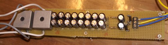
sorry for the late answer.. I tried to change the two diodes with a couple of ones with more wattage, but still no change: I read 13.2V on the output, I can smell something nasty over the diodes, and they get hot, even the last two caps 100uF, 64V get hot! What is going on? Anyway the sound is great and the thing is correctly powering your small pre-amps, but I do not dare to keep them powered on more than a minute.. I also am using a test bulb before the trafo, just to make sure nothing is cabled wrong.. no light in it.. cluesome..
This time I attach you also a picture of the PSU.. I assembled it all straight.. so there are three straight lines on the bottom side of the PCB (interrupted at the two 0.5w resistances..
)..Thanks,
tent:wq
Attachments
to tent,
mjf suggestion is great.
look the photo i think your connection is correct.
the read 13.2v on the output is normal.my psu is 13.1v on the output.
i still have no idea why the 100uf 64v cap is getting hot.i wonder if the zeners and caps is getting hot without laod?
Zang
mjf suggestion is great.
look the photo i think your connection is correct.
the read 13.2v on the output is normal.my psu is 13.1v on the output.
i still have no idea why the 100uf 64v cap is getting hot.i wonder if the zeners and caps is getting hot without laod?
Zang
to tent,
mjf suggestion is great.
look the photo i think your connection is correct.
the read 13.2v on the output is normal.my psu is 13.1v on the output.
i still have no idea why the 100uf 64v cap is getting hot.i wonder if the zeners and caps is getting hot without laod?
Zang
Hi all,
good idea yeah.. I'll try with a 22ohm (or maybe the important is to upgrade it from 0.5W to some 1 or 2W ?). Anyway the voltage drop I measure is: 31.1V before and 26.6V after the res (I'm measuring between upper and lower rail instead of with gnd for practicity..
)Anyway I was thinking that after the zeners the voltage on the output should have been 12V anyway, or no? not 13V...
And yes.. they seem to get hot also without load.. I just tiread without load.. maybe it gets some more time to get hot.. but can be an impression..
tent:wq
- Status
- This old topic is closed. If you want to reopen this topic, contact a moderator using the "Report Post" button.
- Home
- Amplifiers
- Chip Amps
- universal chip pre-amp project