Hammond Mfg. - D.C. Filter Chokes - Enclosed & Potted Versions (193 Series)
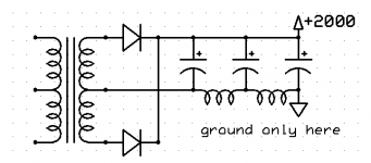
look at lclc than lc filter
this gets decreasing ripple with increasing current (impossible for simple lc)
why those chokes you mentioned? paraleling inductors decreases inductance a lot
look at lclc than lc filter
this gets decreasing ripple with increasing current (impossible for simple lc)
why those chokes you mentioned? paraleling inductors decreases inductance a lot
Here's what there should be for power if that previously mentioned transformer is used. This also uses other parts on hand.
It's probably a good idea to work out what they originally had as far as parts and voltage-current-ripple levels, and then move forward on what may need changing based on different tubes, and also PT.
PSUD doesn't do 3-ph rectification, so any ripple and peak/rms diode current levels will be in significant error if translating simplistically to 1-ph requirements. I have a spreadsheet that can assess these levels if you can clarify the original parts and levels. That AWA datasheet indicates 3-ph secondary winding phase voltage, and the secondary is in a floating star configuration. Can you confirm L1 value and if C11 (2M) was 2uF.
Do you have any confirmed levels of what +6 rail voltage and max average current levels were, and even likely idle current level (-5 rail voltage)? Is B17 a thermal warm-up switch of some kind, to delay the energisation of Re1, and hence +4 rail being applied to drive?
Ciao, Tim
The three 400mA inductors were parallelled for the simulation because the plate current on a pair of 4-1000's at 3000-4000V and making 2KW in AB2 is about 1.1A (one can see the grounded grid spec or the modulator spec). The QB5/750's have no data for 3KV, but at 4KV have to be driven in AB2 to make the power rating. The QB5 is a smaller tube, but larger than the 3-500Z. It's probably impossible to find in cheap supply too.
The only >1 Amp single inductors I have (9H 1.5A) are reserved for a 3CX3000A RF amp. - Except for a 3H 3.5A one from a 5KW RCA transmitter, which is too big for this project (anyone need that size? U pick up in Texas.).
There is no more information about voltages or parts values at this time. I'm working on that. I can confirm the HV filter cap was 2uF (2M=2 million picofarads). Don't know about the choke.
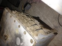
Keep in mind the power supply stuff I posted is just a rough working point, for investigating the types of components needed. This is because there s a stack of 'good-sized plate iron' here. Since it has to be single phase, the values in the original will have little in common with the new ones. The filter size will be mugh larger physically, but I may be able to use electrolytics or to buy modern oil filled caps and a "dahl" inductor if space is tight. The voltages are what have to be close. I can only speculate the HV is 3-4KV. None of the original parts are available although someone says they have the LV transformer removed from this amp. Amazing.
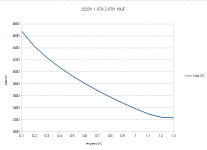
I don't like that chart much. The regulation is poorer than I am used to. I'll have to try another idea. I'm cheap so buying a 1A inductor that will operate at 3-4KV is going to hurt.
I'm willing also to run at the lower of voltages on the old transformer, as a cautionary measure. The OPT inductance and turns ratio has not been measured yet. The primary DCR is 250 Ohms in entirety. That's not very helpful but every thing counts.
Thanks,
Patrick
The only >1 Amp single inductors I have (9H 1.5A) are reserved for a 3CX3000A RF amp. - Except for a 3H 3.5A one from a 5KW RCA transmitter, which is too big for this project (anyone need that size? U pick up in Texas.).
There is no more information about voltages or parts values at this time. I'm working on that. I can confirm the HV filter cap was 2uF (2M=2 million picofarads). Don't know about the choke.
Keep in mind the power supply stuff I posted is just a rough working point, for investigating the types of components needed. This is because there s a stack of 'good-sized plate iron' here. Since it has to be single phase, the values in the original will have little in common with the new ones. The filter size will be mugh larger physically, but I may be able to use electrolytics or to buy modern oil filled caps and a "dahl" inductor if space is tight. The voltages are what have to be close. I can only speculate the HV is 3-4KV. None of the original parts are available although someone says they have the LV transformer removed from this amp. Amazing.
I don't like that chart much. The regulation is poorer than I am used to. I'll have to try another idea. I'm cheap so buying a 1A inductor that will operate at 3-4KV is going to hurt.
I'm willing also to run at the lower of voltages on the old transformer, as a cautionary measure. The OPT inductance and turns ratio has not been measured yet. The primary DCR is 250 Ohms in entirety. That's not very helpful but every thing counts.
Thanks,
Patrick
Well done Patrick for soldiering on - top marks.
My thoughts are that going down in choke henry value, and moving to LCLC or CLCLC would certainly make sense. MOV and resistive shunting of the chokes can control resonances and spikes. Chokes in the 0V line can alleviate voltage withstand ratings.
Not many appreciate that fluorescent light chokes can make great high current chokes - albeit at low-Henry value, but amazing cheap and accessible. When I looked at them I was focussing on the smallest physical chokes I could identify (which came in at 1H and 0.5ADC) - and they were double insulated construction and rated for 240VAC. Similarly, I've found up to 10uF 350VAC MPP film caps in old UPS equipment that would series up nicely for 1-2uF in a very cheap format. Perhaps a low L, low C first filter section would significantly reduce the peak diode current level (if you really wanted to go valve rectifier) and hence alleviate the peak mains current stress.
Last edited:
why worry, he is not playing with 20kg of plutonium or whatnotmon ami opcom, what the heck are you gonna do with that?
Maybe you might consider a giant loop antenna and direct VLF RF?
Otherwise you need the shaker table and connect a really really big planar surface, like 20ft or more per side and let it rip!!
_-_-bear
not this wayI don't like that chart much. The regulation is poorer than I am used to. I'll have to try another idea. I'm cheap so buying a 1A inductor that will operate at 3-4KV is going to hurt.
Attachments
Hi Patrick,
you got the major parts for a huge tube amps. Congratulations! All the main components. thats great!
The plate voltage in the Philips EL6472 is 4750V+. The amp run with its original mains trafo on three phase mains at 127/220V or 220/380V (240/415).
The power consumtion is app. 4,5kVA at full blast. It should possible to made a single phase power unit for the amp. But at 115V mains, the amperage would exceed 40 amps.
Here are the link to the full manual:
http://dl.dropboxusercontent.com/u/25758490/EL6472.pdf
The text is in dutch language. The schematics contains most voltages, others are in the discription.
I know that anywhere around the internet is english version availabe. But I didn´t found it by now.
Let us inform how the monster grow up!
73 Wolfgang
hpeter, That is OK for the DC level but the choke may have 4-5KV peak across the winding, could arc/short inside. Even so, a lower DC rating might be usable in that circuit. Some safety measure is needed in that circuit in case a choke becomes open.
Wolfgang, I owe you a debt! Thank you!
Verstarker. It is that. I like the word.
Wolfgang, I owe you a debt! Thank you!
Verstarker. It is that. I like the word.
Bear must know, it is not a modulator, and there is only one unit, therefore it must be a subwoofer amp! What to do with it? I can figure that out if it is able to get running! Someone else is found the LV/filament transformer and the front panel (in poor cond.).
A challenge is for the cooling of the output tubes. The original QB5/750s only required a fan.
The 4-1000As need a blower and special socket and chimney.
A challenge is for the cooling of the output tubes. The original QB5/750s only required a fan.
The 4-1000As need a blower and special socket and chimney.
Versterker! I mis-spelled. Looks like 5 Ohm output 100V.
True I can not read Dutch but some small translation comes naturally from the technical material.
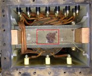
However look at the OPT here. It has a few more secondary terminals, so there will be more checking to do. This is called "the fun part" of the project.
In Figure 10 and 11, it uses the letter "W" when describing the windings. I am not sure what "W" means in this case. It is perhaps a Dutch or maybe a general European designation.
In the figure for the power transformers, it uses "V" for Volts. (fig. 8 and 9)
In the figures, the 'omega' symbol is used for DC resistance.
Very good reading. It is not clear where the secondary wiring goes, except perhaps to the front panel? There are items marked VL1, VL2, VL3, VL4, VL5, VL6. Are these sockets or plugs? More reading. Google translate Norman coordinate.
True I can not read Dutch but some small translation comes naturally from the technical material.
However look at the OPT here. It has a few more secondary terminals, so there will be more checking to do. This is called "the fun part" of the project.
In Figure 10 and 11, it uses the letter "W" when describing the windings. I am not sure what "W" means in this case. It is perhaps a Dutch or maybe a general European designation.
In the figure for the power transformers, it uses "V" for Volts. (fig. 8 and 9)
In the figures, the 'omega' symbol is used for DC resistance.
Very good reading. It is not clear where the secondary wiring goes, except perhaps to the front panel? There are items marked VL1, VL2, VL3, VL4, VL5, VL6. Are these sockets or plugs? More reading. Google translate Norman coordinate.
Attachments
Imho, stress on the chokes at power up, and for faults, can be managed without pedantically requiring a 5kV insulation withstand rating, or 5kV type surge voltage rating across windings.
A single or multi-stepped soft-start, or triac - with interlocking to output stage operation - would reduce choke stress. Parallel resistance and MOVs would constrain any resonant and spike behaviour across the choke winding.
I would also suggest using series ss and valve diodes if the aim was still to use valve diodes - this would certainly improve reliability. I am not sufficiently aware if there are any different reverse bias characteristics with those larger valve rectifiers.
The OT appears to have simple secondary-primary interleaving, but the photo doesn't clearly show where the centre B+ CT bushing connects to the winding?
I'll check with a colleague about the oil type we use in HV PTs.
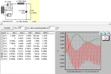
The steady state operation in simulations using a 20H choke input circuit, or the example one, reveals the high voltage impressed across the inductance every half cycle. For this reason and because of having made practical measurements in this sort of high voltage power supply, I disagree and will explain so that it is clear.
Such repetitive voltages are common across chokes in real HV supplies. The repetitive voltages across the windings are scaled with the voltage to be filtered. I have not noticed pedantic assertions regarding the choke's ability to withstand a high voltage across the inductance, so the adjective can not be applied. Regardless of where it was directed, I'd rather ignore it now because it is not important to the fact that surges affect differently the steady state waveform across the choke and the instant voltage between any part of the winding and case/ground.
The simulation below is much like the measured activity in a real 3KV 800mA supply in weekly use here. It shows that upon turn-on, there is a surge on the (nominal 3200V) B+ line and indeed the average DC level on the choke, but the repetitive half-cycle voltage waveform across the inductance is fairly constant at about 5KV. That voltage is necessary for the filtering operation. A spark gap across the winding is one practical protection method against intra-winding arcs at these voltages.
The only reason to place the choke in a ground return lead is to protect its winding-to-case rating from surges.
Some experimenters keep the choke in the + lead and mount it to a 1" piece of wood or by ceramic insulators. This is most common with old or abused, but still working, parts that would be costly to have rebuilt or to buy.
It becomes a moot point if the choke is prevented from shorting to ground but can't stand the steady waveform across its inductance.
PJ
Attachments
In Figure 10 and 11, it uses the letter "W" when describing the windings. I am not sure what "W" means in this case. It is perhaps a Dutch or maybe a general European designation.
In this case, it stands for "windingen" or "wikkelingen" wich translate boths as windings
PJ - I completely agree with the need for a suitably rated choke working voltage.
I was proposing the riskier use of cheap lower working voltage rated chokes. That would mean using chokes in series, and using a multiple stage filter such as a CLCLC to apportion the working voltage across say 2 stages, and using soft-start to suppress overshoot on DCV. It certainly looks like a tall order to try and configure 300-400Vrms working voltage chokes (eg. flouro chokes rated for 240VAC +10%), as just to cope with steady state levels and using 2 chokes in series for each L section would only scale to something like a 2kVDC output application, whereas you are aiming for 3kV or more DCV.
We used Shell's Diala BX oil for LV/MV transformers in the past.
how big voltage can appear, if in general, chokes DCR is expected <200ohmhpeter, That is OK for the DC level but the choke may have 4-5KV peak across the winding, could arc/short inside. Even so, a lower DC rating might be usable in that circuit. Some safety measure is needed in that circuit in case a choke becomes open.
Wolfgang, I owe you a debt! Thank you!
Verstarker. It is that. I like the word.
DCR needs to be fairly low to constrain temperature of choke. A choke would need to be physically quite large to sustain say 1A DC with say a DCR=200.
Any dI/dt higher than what is experienced in a sine wave will introduce an increased voltage across the choke. Diode conduction start and stop can be a problem, which means the first choke in a multi-section filter can have a spikier working voltage than latter chokes. Turning off the mains at the peak of the voltage waveform can also be a problem, as will step load changes.
C or RC snubbers or MOVs across the PT secondary windings and choke, and MOV across the primary winding, are typically used in lower voltage applications to suppress such transients.
Last edited:
Hi ,
These items are normal fuses. They are fitted in the frontpanel. These are the same type of fuses as we had in the fusebox at home before CBs. replaced them.
See also fig.2 , page 20 of the manual.
73
Wolfgang
There are items marked VL1, VL2, VL3, VL4, VL5, VL6. Are these sockets or plugs? More reading.
These items are normal fuses. They are fitted in the frontpanel. These are the same type of fuses as we had in the fusebox at home before CBs. replaced them.
See also fig.2 , page 20 of the manual.
73
Wolfgang
- Status
- This old topic is closed. If you want to reopen this topic, contact a moderator using the "Report Post" button.
- Home
- Amplifiers
- Tubes / Valves
- Unholtz-Dickie amp, 4-1000's