Fuse
Why do you suggest a T3A fuse as opposed to the one mentioned in post #478 Blue? What about the primary fuse? Would you reccomend one of them?
Cheers Cobber.
Yes.
Depends on the speaker impedance and how much capacitance your power supply has. Something like 12 W into 8 Ohm.
You will not be able to control that.
If the transformer is rated for 3 A, you can use a 3 A slow-blow fuse on the secondary side. You don't gain any safety by using a smaller fuse.
Use a split supply. You save on the virtual ground circuit and the output capacitor.
If you regulate it down to 13 V, you will only get 7-8 W into 8 Ohm, instead of 12 W. The regulators will produce a lot of extra heat, extra consumption, and they will increase the cost, size and complexity of the project.
No, you would skip the center tap, so your transformer will have 1x24 V instead of 2x12 V and the regulated voltage could be 26 V, too.
Split supply is better, but the difference is not that big. You basically add a big capacitor to the signal path, and that can or cannot have an influence on the sonic signature.
Why do you suggest a T3A fuse as opposed to the one mentioned in post #478 Blue? What about the primary fuse? Would you reccomend one of them?
Cheers Cobber.
If you have a transformer rated for 2,8 A, use a 2,8 A fuse, if you find one. If you have a transformer rated for 3 A, use a 3 A fuse. Using a smaller fuse than nominal does not hurt, but it does not help either. On the contrary, although it appears strange, transformer secondaries are usually fused with the next higher fuse, e.g. a 3 A transformer would get a 3,15 A fuse, not a 2,5 A.
Why is that so, when we usually always take the next smaller fuse? Because the power rating of a transformer is a guaranteed performance promise. If you use a smaller fuse, the transformer cannot deliver that power, because the fuse will prevent it from doing that. Accordingly transformers are designed to work on the next higher available fuse size.
It is quite common to find a recommendation for the primary fuse on the transformer itself. Sometimes you also find it in the datasheet.
If the transformer manufacturer does not recommend a primary fuse, you will have to determine it by trial-&-error.
Hello there....
Im currently building dual mono lm1875 ( two transformers with two rectifier, transformer is dual secondaries ) and 1 stereo pre amp ( 1 transformer CT )
And im using two outputs ( 4pc binding post and headphone out through one rotary switch ) and im using 4 inputs ( 4 pair rca through 1 rotary switch ) and im using 1 chassis for all of that
can i use stargrounding at post #66 as well ??? Thank you
Last edited:
Thank you for replying, but that thread seems dont answering my question...
would you mind to give me an advice for the grounding
please click on my problem
http://www.diyaudio.com/forums/chip-amps/215555-huge-dc-offset-2.html#post3085101
thank you
please click on my problem
http://www.diyaudio.com/forums/chip-amps/215555-huge-dc-offset-2.html#post3085101
thank you
Sorry, what is henry ott ???")
Henry Ott Consultants
Electromagnetic Compatibility Consulting and Training
home page
Ground loop in stereo amp with 1 transfo and dual PSU
Hi there,
I have gone quickly through this thread and tried some proposals, but sofar no succes.
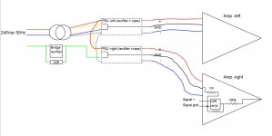
My situation: I'm having two amplifiers with each there own rectifier and cap's, but only one heavy toroidal transfo. Each amp is running perfect and is death quit. But when I'm plugging in both RCA cables comming from a source, there's is slight hum comming out on both speakers. This seems like a ground loop to me, however, I don't see where. The signal ground and power ground are connected on the amplifier pcb by a 10R resistor.
Please have a look at the wiring sheme below. What should I do to get rid of the hum?
Greetz
Hi there,
I have gone quickly through this thread and tried some proposals, but sofar no succes.
My situation: I'm having two amplifiers with each there own rectifier and cap's, but only one heavy toroidal transfo. Each amp is running perfect and is death quit. But when I'm plugging in both RCA cables comming from a source, there's is slight hum comming out on both speakers. This seems like a ground loop to me, however, I don't see where. The signal ground and power ground are connected on the amplifier pcb by a 10R resistor.
Please have a look at the wiring sheme below. What should I do to get rid of the hum?
Greetz
Attachments
Last edited:
That's a tough one. Make yourself aware that the signal grounds for both amps will be connected at the source. Then each of them goes through a separate 10 Ohm resistor to its PSU. On the transformer side you connect the grounds together again. From there you go through another 10 Ohm resistor to the chassis. Is the chassis connected to PE and through that to the source ground, too?
Start by using only one PSU for both amps. Produce a star ground between PSU and amps, and connect the chassis there. Replace the 10 Ohm resistors between signal and power ground with jumpers, if possible. Then add the components back in one by one and check each time.
Start by using only one PSU for both amps. Produce a star ground between PSU and amps, and connect the chassis there. Replace the 10 Ohm resistors between signal and power ground with jumpers, if possible. Then add the components back in one by one and check each time.
Sorry for drudging this topic up again, but I spent all day reading this thread as I am building a mono block with separate PSU
Earlier in this thread the follow was presented.
No one seemed to dispute this and it looks correct to me.
However, the following :
Which one is correct? Would a 5th wire be needed to connect the end of the safety ground back to the SLB from amp to PSU in the configuration shown above?
Also, if the amp and PSU were stacked and the cases were touching would this cause a ground loop for earth ground?
Earlier in this thread the follow was presented.
No one seemed to dispute this and it looks correct to me.
However, the following :
Hi 454,
You will need a minimum of four wires in the cable: safety ground, + voltage, - voltage and power common (0 volts) no matter if you have an SLB or not, of if you have an SLB, where it goes.
Good grounding practice would have five wires if the SLB were in the power supply chassis, and four wires if the SLB were in the amplifier chassis.
If you want to use an SLB, you can not double duty the power common and safety ground because these are what you want to isolate with the SLB. Also, as I said before, it is not a good idea to double duty any ground wiring.
If the secondary of the power transformer is shorted, that short will be reflected onto the primary and the main fuse will blow. There is no need for an additional fuse to protect the transformer.
Dave
Which one is correct? Would a 5th wire be needed to connect the end of the safety ground back to the SLB from amp to PSU in the configuration shown above?
Also, if the amp and PSU were stacked and the cases were touching would this cause a ground loop for earth ground?
There is an old method for audio ground we used while I was in the military, and I've seen it in several audio systems. Its the 1 ohm resistor signal ground. What this does is help isolate your audio ground and when I say isolate I mean DB isolation. So static and RF interference is pushed ever so gently away from the audio. Have you ever heard of this technique?
There is an old method for audio ground we used while I was in the military, and I've seen it in several audio systems. Its the 1 ohm resistor signal ground. What this does is help isolate your audio ground and when I say isolate I mean DB isolation. So static and RF interference is pushed ever so gently away from the audio. Have you ever heard of this technique?
Yes - except I thought the value to be used was 10ohms?
Regards,
Andy
What is SLB that you and Davenport refer to?.........................Which one is correct? Would a 5th wire be needed to connect the end of the safety ground back to the SLB from amp to PSU in the configuration shown above? .............
No, you cannot................As you have done the safty chassis heart ground , the only important things! you can float your signal/psu ground....(ie disconnect Psu1/2 from your green line) .............
All exposed conductive parts must be connected to Safety Earth.
That includes the amplifier chassis and the amplifier control knobs and the input and output terminals and screws through chassis walls and the remote end of an interconnect that your toddler could put in their mouth since the nice red thingy on the end looks just like ......
There was a good set of posts in another Thread that explained where the various GROUND LOOPS could occur and why they would benefit from added resistances in some of the star grounding links.There is an old method for audio ground we used while I was in the military, and I've seen it in several audio systems. Its the 1 ohm resistor signal ground. What this does is help isolate your audio ground and when I say isolate I mean DB isolation. So static and RF interference is pushed ever so gently away from the audio. Have you ever heard of this technique?
I cannot recall the author nor the Thread.
But the jist was to reduce the loop current sufficiently that the remaining current and the loop resistance resulted in a much reduced interfering voltage.
In a stereo set up there are many loops and each loop needs attention to get that reduced interfering voltage
- Home
- Amplifiers
- Power Supplies
- understanding star grounding