Wow, that got really heavy quite fast. ") I will have to save this thread for further study and try to get hold of some of those texts that you guys have referenced. Let me get your take on some fooling around I did over lunch today.
I will have to save this thread for further study and try to get hold of some of those texts that you guys have referenced. Let me get your take on some fooling around I did over lunch today.
Using these 6LR8 curves (same as 6LU8):
Ignore the load line on that graph as it is from another project. I used the methods described here to check out a couple of bias points with 8K a-a load.
loadmatch4-pp-beamtetrodes
I ran the numbers at a bias point of 300Vp and just under 50mA Ip. I came up with about 19W full power with about 7W being class A. I ran some other points as well and it appeared that around 25W was possible at 350V.
The interesting thing is that, if I am understanding the method correctly, the idle current does not really seem to effect the maximum output power as the class AB power calculation uses only the class B load line which is determined only by the load impedance (1/4 Zp-p) and the maximum plate voltage. The non-intuitive result seems to be that running the tube "hotter" (at the same plate voltage) does not increase power output but only moves the class A load line up and down which will effect the total amount of class A power available before transitioning into class B. Presumably this would also effect the smoothness of the transition in some way but I am unclear on exactly how.
So by the looks of it I can play plate voltage against idle current to trade total power for greater "undistorted" power or trade "undistorted" power for tube life. Sort of like a "Low bass, high efficiency and small size... pick any two" type situation.
Does it sound like I am using the method correctly? Am I interpreting the results right?
Seems like I would be wise to use fixed bias so I can diddle with it to get the best combination for my situation.
I will have to save this thread for further study and try to get hold of some of those texts that you guys have referenced. Let me get your take on some fooling around I did over lunch today.Using these 6LR8 curves (same as 6LU8):
Ignore the load line on that graph as it is from another project. I used the methods described here to check out a couple of bias points with 8K a-a load.
loadmatch4-pp-beamtetrodes
I ran the numbers at a bias point of 300Vp and just under 50mA Ip. I came up with about 19W full power with about 7W being class A. I ran some other points as well and it appeared that around 25W was possible at 350V.
The interesting thing is that, if I am understanding the method correctly, the idle current does not really seem to effect the maximum output power as the class AB power calculation uses only the class B load line which is determined only by the load impedance (1/4 Zp-p) and the maximum plate voltage. The non-intuitive result seems to be that running the tube "hotter" (at the same plate voltage) does not increase power output but only moves the class A load line up and down which will effect the total amount of class A power available before transitioning into class B. Presumably this would also effect the smoothness of the transition in some way but I am unclear on exactly how.
So by the looks of it I can play plate voltage against idle current to trade total power for greater "undistorted" power or trade "undistorted" power for tube life. Sort of like a "Low bass, high efficiency and small size... pick any two" type situation.
Does it sound like I am using the method correctly? Am I interpreting the results right?
Seems like I would be wise to use fixed bias so I can diddle with it to get the best combination for my situation.
Attachments
Been waiting for George to chime in. I think he has gotten well over +50% on some exceptional tubes. But then you have to wonder how long they will last when they start glowing!
NOT LONG! Operating any tube in the glow region in an invitation to a short unhappy life. Some tubes can be run hotter than others. If all of the materials used in the construction were nearly pure (Bendix Red Bank) then a little glow wouldn't hurt. If the plates were made out of melted down Corollas (early Chinese tubes) then the tubes wouldn't last long.
When the plate starts glowing (or even before glow) impurities in the materials will be outgassed contaminating the vacuum. This will lead to grid current and possible tube runaway. Some impurities can poison the cathode reducing emission.
When the screen starts glowing two possible things can happen, both real bad. When the grid glows it can deform or melt since the wires are small. The obvious consequence is a short. Yes I have seen it happen. Sweep tubes usually have G1 and G2 close together, making shorts a real possibility. Due to the close proximity the screen usually has a low voltage rating on sweep tubes. It is not uncommon to see the screen run at 150 volts or so while the plate sees 500+ volts. This leads to another failure mechanism. When the screen starts glowing it can emit electrons. When the plate and screen are at the same potential, this is of no consequence. When the plate is several hundred volts more positive than the plate, a strong uncontrolled current flow from a glowing screen to the plate will occur. This will destroy the tube and screen supply components in short order.
OK, so we don't want glow, at least not for long. How is it than we can bend the ratings?
Some other issues to consider. Even within the same tube type, you will find different size plates, presence or absence of grid cooler fins, different plate construction/material/surface finish.
There are vast differences between two tubes of the same number. I have seen two tubes with the same numbers on them with at least a 2 to 1 difference in power handling capability. Why?
First off look at what the sweep tube does. It moves an electron beam across the face of a CRT. It does this at full power every minute that the TV set is on. There is no volume control on the sweep circuit. When many of these tubes were designed most houses had only one TV and it got used a lot. Even in Miami most houses did not have AC. We didn't get AC until the mid 60's. So the tube ran full throttle in a hot box, inside a hot house for several hours a day. It is no surprize that the sweep circuits were responsible for most TV failures. Since excess heat kills tubes, sweep tubes get lower ratings than an identical tube used in a less severe service. The thread linked in post # 18 has a bit more information.
I guess they had to linearly sweep both ways, where as the horiz. channel only had to linearly sweep one way? ......Some TV experts around?
Been there done that too......Both sweep sections sweep only one way linearly. Then the CRT beam is switched off (blanking) while the beam is returned to the starting point (retrace). As mentioned the vertical sweep tube does indeed run class A. In fact it is a SET class A audio amp. Some bigger TV's used pentodes (SEP). It needs to run at only one frequency (60 Hz in NTSC), but many vertical sweep amps did indeed cover the entire audio spectrum. I made guitar amps by copying the vertical sweep section from a TV set way back in the 1960's. In fact the original Bottlehead SEX amp is indeed a vertical sweep amp, including the OPT!
The horizontal sweep amp has another function. It sweeps the beam AND it generates the high voltage. A 25 inch color TV runs about 25 KV at 1 mA. This alone is 25 watts of output. Well you don't get 25 watts out of a Class A SET easilly, so the Horizontal Output Tube is NOT linear. It is a switch. The HOT is either cutoff, or operating as a CCS. This is why the HOT is always a pentode. The HOT feeds its constant current into a flyback transformer, which functions like an automotive ignition coil on steroids. The current charges the coil, and then the current is switched off generating a big voltage spike that is stepped up and rectified to make HV.
Both types of sweep tubes saw a hard life and died young. The tube manufacturers worked to improve their tubes to reduce failures. This involved better materials, thicker and bigger plates, and heat radiating fins welded to the plates and grid rods. This means that there may be several versions of the same type number from the same manufacturer that have different power handling capabilities even though the specs are the same.
How do you know hard you can push a given tube? You must test. In most cases the 20% number mentioned is a given, since that is about the derating factor for sweep tubes. This is concerning plate dissipation only. The screen grid voltage rating is a wild card with sweep tubes. Some tubes will go unstable when the rating is mildly abused and some others of the same type number may be violated by a hundred volts or more.
Using these 6LR8 curves (same as 6LU8):
I beat that one rather heavilly and found some strong ones and some wimps here:
http://www.diyaudio.com/forums/tubes-valves/125963-spud-anyone.html?highlight=spud
So by the looks of it I can play plate voltage against idle current to trade total power for greater "undistorted" power or trade "undistorted" power for tube life.
In a class A amp the tube dissipation is worst case at idle and goes down as the output power goes up. You set the bias as a trade off between tube life and distortion, damping factor and harmonic make up. The bias current has only a minor effect on power output. Due to its effect on damping factor higher tube current can clean up sloppy bass. This is why I craank the KT88's in my Simple SE to 100 mA!
In an AB or B amp the maximum dissipation is never at idle and may or may not be at maximum power output. This depends on the tubes and the load impedance. It can be measured. It is not advisable to exceed the rated dissipation at idle, since things will only get hotter as the volume gets cranked.
"So it can take advantage of averaging and the crest factor to handle above rated power on peaks."
Consider my extreme cranking of the red board. See post # 425 in this thread:
http://www.diyaudio.com/forums/tubes-valves/151206-posted-new-p-p-power-amp-design.html
The 35LR6 is specced at 30 watts. Red glow on these Sylvanias sets in at about 55 watts. The idle dissipation is set to 22 watts per tube. The tube dissipation goes up as the power output increases and tube dissipation is maximum at max output power. The board makes 250 WPC! Tube dissipation is 62 watts per tube at this power level. This is clearly way over spec. If this amp was being used to make continuous sine waves clearly a meltdown would be imminent. So, we don't listen to sine waves do we? Even highly compressed music has a crest factor (or peak to average power ratio to us cell phone designers) of at least 10 db. This means that if I crank this amp to the edge of clipping the AVERAGE power output will be less than 25 watts. Its the average power that melts tubes, so for all musical applications (even a guitar amp) this 250 WPC amp will not melt and the tubes will live long and prosper!
"and try to get hold of some of those texts that you guys have referenced. "
I've attached the diagram from Terman's book on projected cutoff biasing. The Terman book I quoted earlier has just a brief synopsis of this method. It refers back to his earlier book: "Radio Engineers' Handbook" p. 384 (1943) for a complete workup. But its simple enough to get from the diagram. The second tube would have its curve flipped and reversed below the bottom graph axis. The curves then get slid around on the axis until the projected cutoffs line up. The symmetry reached then sums the curves to give a near straight line composite curve for both. So you really just have to select a screen grid V specific plate current versus grid1 V curve off the data sheet, and then do the line projection to get the grid bias. 6LU8 pentode curves attached also.
Obviously, some room for interpretation of the projected cutoff line position due to the curvature of the tube curves.
Good to hear from you George. A refreshing perspective on when to expect 250 Watts of sound and when to expect smoke and flying parts as usual.
Attachments
Last edited:
Good to hear from you George. A refreshing perspective on when to expect 250 Watts of sound and when to expect smoke and flying parts as usual.
I sort of dissappeared from the audio world for almost a month since Sherri was in town. I don't see her much lately. My workbench has been dark and any post I sent except for last nights dissertation came from my phone. we completely cleaned out one rental warehouse to save money. Some of the "stuff" will go on Ebay soon.
If no more wild cards come my way I should be able to resume my usual antics this weekend. I have 3 Simple P-P amps partially completed, and Pete sent me a shiny new red board so I can build a bigger one than his and document it in the red board thread. Two different people have directed me to a web site of an amp builder that claims to be running EL84's on 700 volts. I find it hard to believe so I am going to find out just how much I can squeeze out of a Simple P-P! Smoke and flying parts are a given.
Thank you for the discussion which continues to be very informative. Was I correct that given a specific plate voltage in a class AB amp the bias current will not affect total power output but only the portion that is class A?
George, in your experience would a 6LU8/6LR8 be up to running 400V on the plate (120V screen) with 25mA plate current as a class AB bias point? Should get about 30W there if my quick calculations are correct. A less ambitious 350V looks good for 25W.
George, in your experience would a 6LU8/6LR8 be up to running 400V on the plate (120V screen) with 25mA plate current as a class AB bias point? Should get about 30W there if my quick calculations are correct. A less ambitious 350V looks good for 25W.
The 6LU8 is happy with 400 volts and probably quite a bit more. The screen voltage may need to be higher than 120 volts to get the grid bias more negative for a given current. This allows more drive voltage to be applied which results in more power. I have only experimented with the 6LR8 in SE mode. I was running them triode wired and got to at least 450 volts without blasting the screen grid. TV sets ran them in pentode mode with 250 to 300 volts on the screen. I fixed a lot of Philco TV's in the early 70's that used the 6LU8 so I played with them then, but those memories have long since faded.
I have seen at least one P-P amp posted somewhere on this forum using these tubes. Search it up.
The bias current in a class A amp has almost no effect on power output, maybe 5%. I have seen some AB amps where cranking the current raises the power a bit more, maybe 20%, and some where raising the current actually reduces the power output. I suspect it has something to do with the load impedance, and the ability of the driver to push the grid positive. Remember if you turn up the current you reduced the negative grid voltage, now you have less room for drive voltage without going into AB2 territory. If your driver can't cope, you lose overall.
Increasing the bias current will allow the output tubes to remain in class A longer, but use up the dissipation headroom in the tubes. It also tends to reduce the higher order harmonics.
Ah, thanks. I did find a couple of mentions and they seem to be in the same territory as I was exploring but at lower B+. Idle currents around 25mA with grid voltages around 16 to 18. Looks like we have a starting point.
Since I was planning on using voltage divider screen supply I could make it adjustable with a pot on the upper side of the divider so that I could easily experiment with different screen voltages. My logic in using the voltage divider is that I can get somewhat more stable screen voltage than a single dropping resistor would provide but without the complexity of a regulated supply for both screen and plate. The screen voltage should vary proportionally (or close to it) with variations in B+.
Since I was planning on using voltage divider screen supply I could make it adjustable with a pot on the upper side of the divider so that I could easily experiment with different screen voltages. My logic in using the voltage divider is that I can get somewhat more stable screen voltage than a single dropping resistor would provide but without the complexity of a regulated supply for both screen and plate. The screen voltage should vary proportionally (or close to it) with variations in B+.
I could make it adjustable with a pot on the upper side of the divider so that I could easily experiment with different screen voltages.
You will be dissipating several watts here - it will require a rather robust pot.
A voltage divider screen supply would have significant "sag" under load - often considered desirable in a guitar amplifier, but probably not appropriate in your intended application.
Since I was planning on using voltage divider screen supply.......You will be dissipating several watts here - it will require a rather robust pot.
Add a Mosfet follower and a capacitor to your voltage divider and you have a stiff but non regulated screen supply. Add a zener doide or a gas tube string (0B2 type) and you have a regulated screen supply. Granted it is not an active feedback regulated supply but for a screen regulator it works great.
Look at the schematic for Petes red board (link in first post):
http://www.diyaudio.com/forums/tubes-valves/151206-posted-new-p-p-power-amp-design.html
The G2 regulator is in the first page of the schematics. R21 is there to lower the dissipation in the mosfet to allow a smaller heat sink. It can be eliminated. The active device (Q2) can be a mosfet, tube (6AS7 is a good choice) or even a properly rated BJT. D6 prevents blowing the fet on turn off. D5, D7 and D8 are the zener string. They can be replaced by a string of gas tubes but the value of R33 should be lowered to provide about 10 mA to the tubes. C22 provides filtering 1 to 10 uF is good. C21 keeps things stable. I used a 10 uF because thats what I had. You can use a pot (1 meg) across the zener string with the wiper connected to R46 to make the voltage adjustable. Don't use a BJT if you use a pot (base current).
Voltage divider will sag more than a simple dropping resistor? If the idle current through the resistor string is several times that of the current drawn by the screen it should be pretty stable shouldn't it? No doubt I would burn some extra watts but I thought that this was not an unusual practice back in the day. Am I wrong on that?
If I regulate the screen don't I have to regulate B+ too?
WRT the SF are you suggesting that a low current reverence divider be hooked to the gate of the FET and then the screen fed off of the source of the FET? Is there a load resistor on the source or just connected straight to the screen. Where would the cap be, just bypassing the bottom resistor in the divider as in a normal divider? Maybe a picture?
Thanks for walking me through this.
If the idle current through the resistor string is several times that of the current drawn by the screen it should be pretty stable shouldn't it?.......this was not an unusual practice back in the day.
Using a voltage divider is OK and was indeed standard practice on low current tubes, or in circuits that ran at fairly low levels in class A. A power pentode in a high power application can have wide swings in screen current. The current will change instantaneously with plate voltage, and it will change slowly. As the overall power level is increased the average screen current will go up. You can put a large bypass cap on the screen, but the screen voltage will still drop as the average power level is increased. This may limit the maximum power output under steady state conditions. It can be made to work with music, but power output measurements can be problematic.
If I regulate the screen don't I have to regulate B+ too?
Usually not. In a pentode the plate current is dependent on the bias voltage (G1) and the screen voltage (G2). The plate voltage has a small effect on plate current. So if you regulate the screen, you should regulate the bias supply, and vice versa. Yes, I know of several amps where the screen is regulated and the other supplies are not. Petes red board is one example.
Maybe a picture?
Don't have a picture handy. Use the schematic of Petes screen regulator for reference.
WRT the SF are you suggesting that a low current reverence divider be hooked to the gate of the FET and then the screen fed off of the source of the FET?
Only Q1, R33, and a resistor in place of D5, D7, and D8. No other parts That will usually work, but it may oscillate. A load resistor from source to ground (R42) helps avoid oscillation if the screen current approaches zero. Set it for 5 mA or so on a big sweep tube.
A capacitor can be placed across R42 (C21). This is usually a good idea. The screen stopper goes between this cap and the screen of the tube. Multiple tubes can run off of one fet. Each gets its own stopper.
There is an issue putting a cap on the gate of the fet (C22). When the power is shut off the gate capacitor will need a path to discharge. Since all of the resistors are high valued, it will try to discharge through the gate of the fet, blowing the mosfet. D6 is added to keep the gate breakdown voltage from being exceeded. Some mosfets have the zener diode inside the fet. D6 may not be needed on these fets.
R6 is a gate stopper. It may not be needed if only resistors are connected to the gate (voltage divider). If any other parts are present, add the stopper.
R21 is probably not needed unless a lot of voltage is being dropped at a high current. This circuit was dropping nearly 200 volts and feeding 4 sweep tubes.
Start with something simple and add whatever is needed for your particular application.
OK, I had a chance to look over Pete's design a little bit this lunch hour. The reference voltage is developed differently but it seems that it is not too dissimilar from one thing that I was considering.
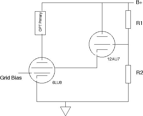
The R1/R2 divider would set up a reference voltage that will be proportional to the B+ voltage and relatively constant if B+ is fairly stiff. The grid of the triode will be high Z so no loading of the divider to speak of. The triode will attempt to keep the voltage at the cathode fairly close to that of the grid and will attempt to supply whatever screen current is necessary to do that. It seems that a smallish resistor from the cathode of the triode to ground would help stabilize the screen voltage even more by minimizing the change in total cathode current out of the triode.
Another possible addition might be a series capacitor/resistor string between the pentode's plate and the triodes grid to apply some local NFB in kind of a mock UL mode.
Attachments
Another possible addition might be a series capacitor/resistor string between the pentode's plate and the triodes grid to apply some local NFB in kind of a mock UL mode.
Some thoughts and experiments were proposed along those lines here. I dont think anyone ever finished anything though.
http://www.diyaudio.com/forums/tube...load-discussion.html?highlight=mosfet+UL+load
OK, I had a chance to look over Pete's design a little bit this lunch hour. The reference voltage is developed differently but it seems that it is not too dissimilar from one thing that I was considering.
The R1/R2 divider would set up a reference voltage that will be proportional to the B+ voltage and relatively constant if B+ is fairly stiff. The grid of the triode will be high Z so no loading of the divider to speak of. The triode will attempt to keep the voltage at the cathode fairly close to that of the grid and will attempt to supply whatever screen current is necessary to do that. It seems that a smallish resistor from the cathode of the triode to ground would help stabilize the screen voltage even more by minimizing the change in total cathode current out of the triode.
Another possible addition might be a series capacitor/resistor string between the pentode's plate and the triodes grid to apply some local NFB in kind of a mock UL mode.
If you're going to do that, then make a proper active decoupler with either a MOSFET or BJT. A 12AU7 is not a real good choice for this since any triode, and especially one with a rather low u-Factor like a 12AU7, won't isolate the screens from the DC rail very well since triode plate current varies a great deal more than either the collector or drain current with variations in voltage appearing at the plate (collector, drain).
Even better would be active screen voltage regulation.
I also found a Zener string and a source follower more than adequate to regulate screen grid voltages.
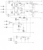
On the schematic you see 400V regulator (driver stage), 270V regulator (GU-50 screens), -72V parametric stabilizer (control grid bias). Gu-50 tubes also, like sweep tubes, are very underrated for audio usage: they were rated for linear amplifiers in transmitters where they were providing sinusoidal output.
Since screen grid voltage is regulated, I strongly advise to regulate control grid bias as well.
Attachments
Hmm.. Just discovered the Altec A340 schematic. They used an interesting approach. The tube regulator is connected between the B+ supply and the screens with a series 100 ohm in series with the regulator. There is no ground reference except through the screens. This drops the screen supply 70V from the plate without actually regulating the screen voltage. For some reason they have a 47K resistor across the regulator tube. I am not sure what that is for but it shunts about 1 1/2 mA around the regulator.
- Status
- This old topic is closed. If you want to reopen this topic, contact a moderator using the "Report Post" button.
- Home
- Amplifiers
- Tubes / Valves
- Under rating of Vertical Sweep Tubes