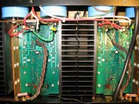
Here's a picture that may help.
The black wire at the bottom is jumpering together the 0V points of the two channels' PCB's. The points at where it connects to the two PCB's are also the points at which the input jacks' shields are connected to the PCB's.
Then there's the second thin black wire that can be seen running alongside the braided output wire on the right. It connects the 0V point of the left channel PCB to the star grounding point in the center of the copper ground bar (the stack of nuts between the filter caps at the center top of the picture).
At the lower left and lower right you can see where this bar wraps around to connect to the - speaker binding posts. On the sides (not visible here) there are some case screws that bolt the case sides to the copper bar. Those points are not insulated.
By the way, I'd be curious to know how much idle noise others are seeing at their speaker terminals with everything hooked up but no signal. What I'm fighting currently at this amp is about 10mV, with the current patch cables, with the amp grounded. This drops to just over 4mV when the amp's ground is defeated.
Cheers,
Paul
Attachments
SQLGuy said:Here's a picture that may help.
The black wire at the bottom is jumpering together the 0V points of the two channels' PCB's. The points at where it connects to the two PCB's are also the points at which the input jacks' shields are connected to the PCB's.
Then there's the second thin black wire that can be seen running alongside the braided output wire on the right. It connects the 0V point of the left channel PCB to the star grounding point in the center of the copper ground bar (the stack of nuts between the filter caps at the center top of the picture).
At the lower left and lower right you can see where this bar wraps around to connect to the - speaker binding posts. On the sides (not visible here) there are some case screws that bolt the case sides to the copper bar. Those points are not insulated.
By the way, I'd be curious to know how much idle noise others are seeing at their speaker terminals with everything hooked up but no signal. What I'm fighting currently at this amp is about 10mV, with the current patch cables, with the amp grounded. This drops to just over 4mV when the amp's ground is defeated.
Cheers,
Paul
It looks OK to me.
That is one hell of an earth wire !
I just use a piece of 13 amp mains cable for mine.
How much nosie do you get with the input shorted out ?
Yeah, the copper bars they used in here are pretty neat. The + and - rails use them as well.
With the inputs shorted, or open, I get about 350uV A/C at the outputs.
The problem I'm having isn't a ground loop within the amp (at least, I don't think it is)... it's ground loop between pieces of equipment in the stereo. I mean, literally, there's a loop: crossover ground through patch cables to amp ground to wall plate ground through mains wiring back to crossover ground again.
SQLGuy said:Yeah, the copper bars they used in here are pretty neat. The + and - rails use them as well.
With the inputs shorted, or open, I get about 350uV A/C at the outputs.
The problem I'm having isn't a ground loop within the amp (at least, I don't think it is)... it's ground loop between pieces of equipment in the stereo. I mean, literally, there's a loop: crossover ground through patch cables to amp ground to wall plate ground through mains wiring back to crossover ground again.
It might be worth trying a ground lift switch in the amp.
On my setup I have a dual cd player going into a mixer then into a power amp. I know the CD player and mixer arent grounded so I only need a ground at the amp.
HAve you tried removing the zero volts connection between the amps and just relying on the connection to ground ?
nigelwright7557 said:
It might be worth trying a ground lift switch in the amp.
The problem there is the ground bar being screwed to the case. I'd have figure out a way to insulate its mounting points so that I could separate the case ground from the power supply / signal ground.
nigelwright7557 said:
HAve you tried removing the zero volts connection between the amps and just relying on the connection to ground ?
No, not yet. I did, though, measure the voltage difference between the outlet ground where the amp is plugged in and the one where the crossover is plugged in, and that was less than 1mV... with the meter wires stretched out as they were, a lot of that 1mV may be getting picked up inductively anyway, so I'm not sure if I can get a good measure of any difference in ground levels.
I think the next step is definitely to put the PS Audio back in place (got the Adcom running right now), and play around with different options for connecting the shields of the patch cables.
IMO, currents shouldn't flow in shields. Since this isn't a perfect world, they usually do, but they should be minimized. A chassis is also a shield. Circuit ground should connect to the chassis at one and only one point, as near to the lowest level input as possible. Mains ground should connect to the chassis close to the AC entry point. In both my pre and power amps I establish a power and ground point close to the circuit boards using a terminal strip with bypasses, then distribute power from there. Ground returns there, with one wire also grounding the chassis from there. Speaker returns must only go to this star ground, never through the chassis. Your supply is closer than mine, so you probably wouldn't establish a new distribution point. The rest still applies. The only hum problems I have relate to transformer fields, which are PITA to fix. Self covers this pretty well in his power amplifier book, though the drawing could be even more detailed than it is. I also find the Ott book, Noise Reduction Techniques in Electronic Systems, very useful.
Conrad Hoffman said:IMO, currents shouldn't flow in shields. Since this isn't a perfect world, they usually do, but they should be minimized. A chassis is also a shield. Circuit ground should connect to the chassis at one and only one point, as near to the lowest level input as possible. Mains ground should connect to the chassis close to the AC entry point. In both my pre and power amps I establish a power and ground point close to the circuit boards using a terminal strip with bypasses, then distribute power from there. Ground returns there, with one wire also grounding the chassis from there. Speaker returns must only go to this star ground, never through the chassis. Your supply is closer than mine, so you probably wouldn't establish a new distribution point. The rest still applies. The only hum problems I have relate to transformer fields, which are PITA to fix. Self covers this pretty well in his power amplifier book, though the drawing could be even more detailed than it is. I also find the Ott book, Noise Reduction Techniques in Electronic Systems, very useful.
Hi Conrad
I have the same PITA like you with toroid x-formers (Greek made toroids = :bs: as well the 90% made in the rest world). I have not any issue of noise without earthing the P.S. ground. I use seperate P.S. per each channel thus the gnd node of each channel is absolutelly seperated from the other channel... but this damned straight magnetic flux radiated from toroids affects the small signal stages.
Fotios
fotios said:
Hi Conrad
I have the same PITA like you with toroid x-formers (Greek made toroids = :bs: as well the 90% made in the rest world). I have not any issue of noise without earthing the P.S. ground. I use seperate P.S. per each channel thus the gnd node of each channel is absolutelly seperated from the other channel... but this damned straight magnetic flux radiated from toroids affects the small signal stages.
Fotios
Why not put a screen between the toroid and the circuit ?
Many valve circuits have the transformers on one side of the chassis and the circuit on the other to screen them.
nigelwright7557 said:
Why not put a screen between the toroid and the circuit ?
Many valve circuits have the transformers on one side of the chassis and the circuit on the other to screen them.
Hi Nigel
I have post a picture of my amplifier in "post your solid state pics" thread, there you can see for what i am talking and to understand better, about the toroid i ordered (the stupid, i paid 25 euros extra for the supposed screen bowl FROM STEEL! which is a good conductor of mag. flux of course). I have tried extra screen from copper foil 0,5mm thick... nothing! I have tried extra screen with alu plate 2mm thick formed cylindrical... nothing!
I discovered that the pcbs are affected from underneath from toroid! I am in war this moment with mag. flux radiation.
Your remark for the place of xformer against the place of sensitive circuits it is correct. But i trusted the constructor of toroid like an idiot.
Thanks
Fotios
fotios said:
Hi Nigel
I have post a picture of my amplifier in "post your solid state pics" thread, there you can see for what i am talking and to understand better, about the toroid i ordered (the stupid, i paid 25 euros extra for the supposed screen bowl FROM STEEL! which is a good conductor of mag. flux of course). I have tried extra screen from copper foil 0,5mm thick... nothing! I have tried extra screen with alu plate 2mm thick formed cylindrical... nothing!
I discovered that the pcbs are affected from underneath from toroid! I am in war this moment with mag. flux radiation.
Your remark for the place of xformer against the place of sensitive circuits it is correct. But i trusted the constructor of toroid like an idiot.
Thanks
Fotios
I have had very few problems with solid state amps and noise.
Once the input is connected to a low impedance source the noise goes away.
I have had serious problems with valve amps and spent many an hour tracking down hum and noise.
Originally posted by fotios
I am in war this moment with mag. flux radiation.
Have you considered putting the transformer outside in a separate case.
Regards
Mike
Well, I'm done-ish with the amp for now.
I played around with the cable shielding a bit, and managed to shave off a couple mV of noise there. The final solution on the cables was a bit rough, though, and I probably won't leave it in place: 1K Ohm termination inside the headshells on the amp end. The crossover's designed to drive 600 Ohm loads, but still....
Even with that, I was getting more ground loop noise than I wanted, so I bit the bullet and rearranged things a bit until I could plug all the grounded equipment (except the Bryston) into one 6-way on-wall outlet adaptor. This helped a lot and brought the insertion noise (with crossover turned off) down to about 150uV (e.g. with the inputs disconnected I get about 350uV noise at the outputs; with the inputs connected, but the crossover off, I get about 500uV noise). Oddly, with the inputs shorted, I get about 450uV noise.
The noise of the power transformer humming is now much louder than any noise from the speakers, and is likely the next thing I'll be looking into. (any suggestions there? It's an EI transformer, and any replacement likely would need to be as well, to fit).
I still plan to at least tack in and try out some balanced inputs, though... and maybe I'll destroy a North African city while I'm at it. ;-)
Cheers,
Paul
Sounds like you've made a substantial improvement, and I'd be amazed if you could actually hear any hum at all. I've also had transformers that physically hum, and it's often a sign that they'll run hot as well. If the transformer doesn't hum suspended in mid air, then there ought to be a way of mounting it so it doesn't hum. Watch out for cover panels that act as a soundboard. A compliant mounting might help, but I like my transformers solidly grounded. A piece of "fish paper", that heavy grey electronic staple fitted between the transformer and chassis might help. Unfortunately I've "cured" mechanical hum problems, only to have them come back a few weeks later :-(
Thanks Conrad,
Yes, here I am talking about mechanical hum from the ransformer, and it does tend to get decently warm after a few hours idling. Are these related symptoms?
Any real cure, or just look for a new one?
I emailed Paraline (who made this one) to see if they had any ideas about rewrapping it or potting it for me. No reply yet... I'll probably try calling them to see if that gets me any further.
Cheers,
Paul
I recently had ground loop problems in a Tri-amped system. I got rid of them using Rod Elliot's Loop Breaker Circuit.
http://sound.westhost.com/earthing.htm
col.
http://sound.westhost.com/earthing.htm
col.
nigelwright7557 said:
I have had very few problems with solid state amps and noise.
Once the input is connected to a low impedance source the noise goes away.
I have had serious problems with valve amps and spent many an hour tracking down hum and noise.
Me, no one as long as i used the old school, trustable, correct made EI type x-formers that i reffer in my post in the other thread. Concretelly, to save money, i ordered a single 800VA (actually its core was 1KVA because the standard dimensions of bobbin) EI xformer with seperate windings per each channel. How to hell, this monster placed close to PCBs did not caused hum or buzz or crackl noise? Probably because the absence of any mechanical noise. As i reported, the finished xformer with the double and earthed belly bands, was dipped into a bath of epoxy varnish contained into a vacuum can. After two days of drying, the E and I laminates forming the core, was firmly sticked between them. Another one important thing was that, because in this workshop constructed xformers for sensitive measuring instruments like medicals, there was except the usual Si-Fe laminates as well special alloy laminates with bigger magnetic permeability. A core made from such type laminates, it needs less magnetizing current consequently the mag. flux is smallest eliminating thus any strong radiation arround.
Michael Chua said:
Have you considered putting the transformer outside in a separate case.
Regards
Mike
Of course this is the absolute cure. But it is not so practical.
col said:I recently had ground loop problems in a Tri-amped system. I got rid of them using Rod Elliot's Loop Breaker Circuit.
http://sound.westhost.com/earthing.htm
col.
col, in Greece the public corporation of electricity uses the same method of "neutral-grounding" like in Oz. This is for economy in power transmission lines. The article of Rod it is very explanatory. One very good source for these issues it is also the site of Bryston. From there, you can download many detailed schematics of amplifiers in which you can see many practical ways of earthing the P.S. gnd, of filtering the neutral conductor from DC components etc. Bryston schematics, are a usefull guide.
Fotios
I'm no transformer designer, but IMHO transformers that buzz and run warm with no load are transformers where somebody cut corners. Either the laminates are not completely insulated from each other, impregnation was bad, the steel is junk, or somebody skimped on windings to save copper. Heat is loss, as is buzz. Good transformers, like children and pets, should be seen and not heard.
Is that still true after 25 years, though? This is not a young transformer. Also, it's not quite no-load... idle bias is still about 100W from the outputs.
Anyway, I contacted the tranformer's manufacturer, and they offered to revarnish it for me if I pay for the round-trip shipping. I'm pretty pleased to see that kind of customer service after this amount of time. I'll pull it in the next couple of days and I'll let you all know how things worked out once it's back.
Cheers,
Paul
SQLGuy said:Is that still true after 25 years, though? This is not a young transformer. Also, it's not quite no-load... idle bias is still about 100W from the outputs.
Anyway, I contacted the tranformer's manufacturer, and they offered to revarnish it for me if I pay for the round-trip shipping. I'm pretty pleased to see that kind of customer service after this amount of time. I'll pull it in the next couple of days and I'll let you all know how things worked out once it's back.
Cheers,
Paul
I wish you success, because i know the proccess of revarnish which is a simple dipping of x-former into an epoxy varnish bath. Also a retightening of the 4 screws in the corners of core. Nothing more. I have only a suggestion for you. After delivering the x-former back to you, don't use it for a couple of days. Leave the x-former in the self so as the varnish dry thoroughly.
Fotios
- Status
- This old topic is closed. If you want to reopen this topic, contact a moderator using the "Report Post" button.
- Home
- Amplifiers
- Solid State
- Unbalanced to balanced input conversion?