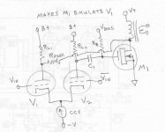
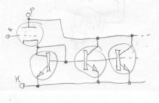
Instead of trying to find some power tube with good and use-able triode curves, you can just use emulation as below. The device M1 can be a power tube (Mosfet shown), and the _LW6 tube would be a good one there. The resulting triode curves however will be matching up to those of tube V1.
It's a simple N Fdbk loop that insures that the final output looks like the Mu of V1 (times the input signal) or else the N Fdbk fixes it. Having a tube with already good triode characteristics for the output just makes the job easy for the N Fdbk. The output tube doesn't even have to be in triode mode, since it is the relaxed spacing between grid1 and cathode that gives the tube its good transfer characteristics for either triode or pentode mode.
Tube V2 would best be a high gain tube for high loop gain for the N Fdbk, and could be either a triode or pentode. More loop gain being helpful if the output device is not reasonably matching the "emulant" tube V1. Especially if M1 were a Mosfet. The higher loop gain will also greatly reduce the final output impedance for a better damping factor.
The whole scheme can be extended for P-P use as well, just use the same setup for each P-P side, with a splitter ahead of the V1 tubes then. The inverted Vin to tube V2 being optional, just DC bias.
With some socket flexibility for the V1 tubes, one could bring tube "rolling" to a whole new level. A variable CCS tail knob adjustment and an oversized V2 tube (like a 10 Watt 12HL7, 21000 gm) would allow the "emulant" tube operating point to be selected for small to big tubes. (possibly needing Gyrators for the V1 and V2 plate loads, or else adjustable RL1 and RL2 loads)
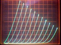
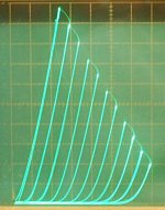
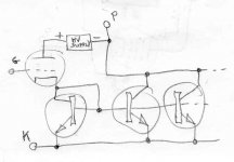
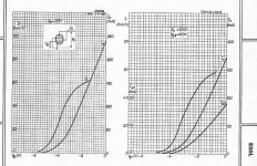
Some cheap emulant tube candidates (pic 2: 1E7G and pic 3: 12HL7):
Well 300B could be used too, but why bother.
Of course, if you already just happen to have two 300B tubes on the shelf, they could be used for the M1 finals. But they require fairly excessive grid drive levels.
It's a simple N Fdbk loop that insures that the final output looks like the Mu of V1 (times the input signal) or else the N Fdbk fixes it. Having a tube with already good triode characteristics for the output just makes the job easy for the N Fdbk. The output tube doesn't even have to be in triode mode, since it is the relaxed spacing between grid1 and cathode that gives the tube its good transfer characteristics for either triode or pentode mode.
Tube V2 would best be a high gain tube for high loop gain for the N Fdbk, and could be either a triode or pentode. More loop gain being helpful if the output device is not reasonably matching the "emulant" tube V1. Especially if M1 were a Mosfet. The higher loop gain will also greatly reduce the final output impedance for a better damping factor.
The whole scheme can be extended for P-P use as well, just use the same setup for each P-P side, with a splitter ahead of the V1 tubes then. The inverted Vin to tube V2 being optional, just DC bias.
With some socket flexibility for the V1 tubes, one could bring tube "rolling" to a whole new level. A variable CCS tail knob adjustment and an oversized V2 tube (like a 10 Watt 12HL7, 21000 gm) would allow the "emulant" tube operating point to be selected for small to big tubes. (possibly needing Gyrators for the V1 and V2 plate loads, or else adjustable RL1 and RL2 loads)
Some cheap emulant tube candidates (pic 2: 1E7G and pic 3: 12HL7):
Well 300B could be used too, but why bother.
Of course, if you already just happen to have two 300B tubes on the shelf, they could be used for the M1 finals. But they require fairly excessive grid drive levels.
Attachments
Last edited:
Sorry for being a little off topic. The emulation scheme has been mentioned many times before in the past, not sure if any were in a thread strictly about it. It just solves so many problems that always come to the fore when power pentodes in triode mode are discussed.
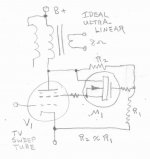
Another approach for using the _LW6 in "triode" mode (triode curves resulting) would be to use a reduced voltage UL scheme. Just an R divider network from plate to cathode, driving a Mosfet (or tube ) follower, which then drives the screen grid. So a UL mode resulting, but with the screen V always below the plate V. (for tube health)
Could also use the UL taps on the OT for the source V's for the R divider networks (P-P).
If, say, 50% of the plate V appears on the screen, then the tube's internal Mu will be doubled effectively. (and the output Z doubled)
Attachments
Last edited:
Well, I could start a new thread on "un holy" pentode to triode schemes I guess. Only a couple of simple ones come to mind (above ones), as mentioned. Will probably get no replies, and then disappear into the dusty archives. Could be useful for a quick link reference occasionally I guess.
Found this earlier post, seems relevant: Alternative Ultra-Linear Connections?
Here's another one:
The Tube Mirror.
Make a small tube into a BIG one, triodes too. Good for OTL.
Provides N x the current output of the original tube.
And a somewhat similar scheme, using a pentode to increase the current output of a triode. Requires getting the current start-up states equalized via bias and screen V selection (for similar current tracking).
Attachments
Last edited:
The Tube Mirror.
Take that one one step further. I used Mosfets for the mirror because I had some.
Use a suitable "ideal" triode for the input tube. Load it's plate with a suitable load for the tube being used used. I used the big side of a 6EM7 with a small 5K OPT with a resistor across its secondary. Apply the usual fixed bias to its grid.....I used a mosfet follower PowerDrive style. Ground the mosfet sources. Tie all of the mosfet gates together with the drain of the input mosfet as in a typical current mirror. Tie the drains of the "mirror" fets together and connect them to the cathode of a suitable BAST, then apply a fixed negative voltage to G1 of the BAST a suitable positive voltage to G2, and connect your real OPT to its plate. The OPT can be fed by a much higher B+ than the little input triode.
Note I had this working with the large side of a 6EA7 triode and a 6GF5 pentode. The mirror was made from 5 identical mosfets so that the 6GF5's plate current "mirrored" the 6EM7's plate current except multiplied by 4. I used these tubes because I had a bunch and didn't care if I blew any up. It worked good.
I tried to scale it up to a 45 triode and a 6HJ5 (6DQ5) pentode with disastrous results. Mosfets and tubes exploded. I put it all on the shelf and gave up.
Later experiments with a totally different experiment followed the same path.....worked good on small tubes, blew up on big tubes. That's when I discovered that some of my 10 ohm sense resistors were really 1 ohm.
I'll get back to these experiments sooner or later.
Why is a power triode so expensive?
It's hard to get in there and remove that screen grid.

Guess the big old power triodes are mostly bought up. You either have to use 2000V transmitting tubes now, or non-linear regulator tubes (always optimized for maximum gm for easy control).
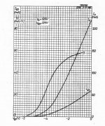
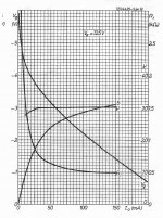
Actually, it's not that easy to find ANY tube (pentode or triode) that is all that "linear" due to gm being optimized (maximized) for most of the later tubes. To get a "linear" triode, the grid 1 needs to follow a 3/2 power law (V to I) like the plate (so tracking). But most tubes have the grid 1 positioned closer to the cathode to get maximum gm, which causes grid wire proximity effects, or "island effect". (inselbildung) That causes grid 1 to have a mostly 2.0 power law, which mis-tracks with the 3/2 power plate or grid 2 internal N FDbk, causing Mu to change with current.
The gm curves given for some tubes gives a good illustration (below, the S labeled curve). Gm being the first derivative of current (versus grid voltage), a 2.0 power law tube will have a linear ramping gm curve (versus grid 1 voltage). What you usually see is a stretched out S shaped gm curve. Indicating higher than 2.0 power law at low currents, near 2.0 power through the mid range, and less than 2.0 power law at high currents, where the cathode is saturating.
The frame grid E55L seems to get excellent grid 1 and grid 2 tracking somehow (constant Mu), and still have a 2.0 power law in the mid range. If grid 2 is spaced (wire pitch) correctly, I guess, one can equalize the "island effect" for both grids.
( last pic, a LV version of the Tube Mirror. Suitable for an OTL amp. )
Attachments
Last edited:
George, i suspect the positive thermal coefficient of vertical mosfets is the cause of the runaway on higher dissipation while similar runaway was prevented by adequate heatsinking on lower dissipation. I think a source resistor or some form of bias servo will help.... Ground the mosfet sources....
I did have a sense resistor in series with the sources.
I mentioned the cause of the exploding parts in my description. The box of resistors contained a mix of 1 and 10 ohm parts while I was under the assumption that they were all 10 ohms. This led me to set the bias at about 10 X the current I was expecting.
Autopsy on one of the exploded tubes revealed an arc from cathode to plate which caused the mosfets, sense resistors and tubes to explode. My big power supply has 1000 uF of output capacitance and it was charged to somewhere in the 600 volt range. That much stored energy makes parts explode.
Dunno… MOSFET exploded is such a hyperbolic response.
Tell you what — this topology, especially outlined in the first hand-drawn schematic — is intriguing. Seems to me tho' that you'd definitely want to “stack your odds of succeeding” by having a relatively low pair of anode resistors for the first differential CCS biased pair of triodes.
You definitely don't want them trotting forth much gain.
Some, sure.
But not huge.
Many MOSFETs have transconductance in thousands of millimhos (thousands of mA per V on gate). Since the source pin of the emulation MOSFET is ground-attached, relative to the gate at least, there isn't room for a whole lotta swing. See why the input section need not have much gain?
I also like the fact that automagically you get phase inversion for free with the differential input pair. Push-pull becomes essentially trivial. The RFBCK as shown can also be doubled up to both sides in the push pull configuration. No need for another tube!
Cool circuit.
I'm'a goin' to build one.
(GoatGuy goes and thinks some) … … … …
Seems like the biggest “issue” is the rather extraordinarily low output impedance, and finding a convenient transformer to act as the output impedance matcher. If I calculate it right, the drain-side output impedance of a Vishay SIHP6N40D-GE3 (400 VDS, 100 W PDISS, TO–220A, 1.7 S) is about 800 Ω with a 225 VB+ on the high side of the output transformer.
800:8 is 100:1, so (ratio = √( 100:1 )) = 10:1. Cool beans. If I were taking KodaBMX's advice about using power torroids as output transformers (why not!), and derating 3× (power) for 25 Hz minimum reasonable response and core lamination saturation, let's see … we'll drive the MOSFET at 75 W nominal dissipation; at 200 VD (losing 25 to the transformer), that's what, 75 ÷ 200 → 370 mA. VG bias point around 4 V. VG-AC swing of only 100 mV … will swing output fully.
A Bell Signal brand "16–12" sounds like just the ticket. 192 VA rated, thus able to deliver more than ¹⁹²/₃ → 64 W of 25 Hz into an 8 Ω load. Much higher power delivery at higher frequencies. Well potted, a quality $85 transformer. The use of negative feedback certainly seems to offer ability to overcome some of using a power transformer instead of a dedicated audio-grade device's full-range frequency shortcomings.
… … …
GoatGuy
Sweep Tubes in Dee Skies...
BAST? = Big A__ Sweep Tube? OK, got some of them.
--------------
On a side note, I once observed the power law for the various grids of some Sweep tubes (measured the curves and then did calcs.), and noticed that grid 2 sometimes had a V to I power law -below- 1.5 !! This seemed odd at first, but then I realized that aligned grids meant that grid 1 wires actually could produce an inverse "Island Effect" by shielding the grid 2 wires where they are closest to the cathode surface.
This actually makes the internal triode mode Mu vary even worse than expected than grid 1 wire proximity effects alone would lead one to expect. Getting a 2.0 versus 1.3 power law mis-tracking. Which may explain why beam pentodes (tetrodes) often get a reputation for having poorer triode (mode) characteristics than real triodes. ( A frame grid 1 and normal grid 2 should eliminate this deleterious alignment effect)
Taking a que from Crazy/Twin drive, is there some way to put this weird effect to better use? (using 2 grids at once, in some way)
1) For grid 2 drive, we might be able drop the grid 2 power law fully down to unity if the grid 1 shielding "anti Island Effect" could be enhanced further. So maybe put a small anti phase V drive to grid 1, while mostly high V driving grid 2. This will however require higher grid 2 drive to get to full power. Not real good.
2) Or, using a sweep tube with a low Rp plate for triode, we might try some in phase drive on grid 2, while mainly driving grid1, to bring the effective ( [1.3 + 2.0] /2) power law of the combined grids down to near 1.5 power law to match the plate's law.
Well, just some hair brain ideas to try out in the Winter, when the snow looks boring outside.
The RFBCK as shown can also be doubled up to both sides in the push pull configuration. No need for another tube!
I think that just ends up being a P-P shunt Fdbk (Schade) driver, since the differential driver emulation gain is drowned out by the low plate N Fdbk loads.
I also like the fact that automagically you get phase inversion for free with the differential input pair. Push-pull becomes essentially trivial.
Yes, could delete the splitter stage by driving opposite sides of the two differential/emulation driver stages.
One should be able to combine the two differential/emulation driver stages together (for P-P) by using a single pentode differential/emulation stage (2 pentodes). The triode emulation N Fdbks come back thru the screen grids then, while the plates still have high gain for enforcing emulation loop gain. You are now required to combine the good triode and high gain factors into a single tube. 12HL7 ($1) and E55L ($45) might be good driver candidates there. Not much tube space for rolling other tubes though.
For the original differential/emulation driver, the single T + P high gm tube 6F12P ($3) might do. Constant Mu triode.
Last edited:
what is your take on crazy drive used on such tubes as the 4-250 tube?
With 300 to 600 V operation of the screen grid, I'd say that's not a reasonable choice for Crazy/Twin drive or G2 drive for that matter. Unless you want to drive it with -another- transmitting tube. It does allow for grid 1 current. Even 10 Watts diss. on grid 1. Would be an exercise in Un-Holy evil design for sure. Try and find an OT for it even. You'll have to parallel them up for a reasonable Zprimary.
Availability of 1000V+ SOT227 devices with max. dissipation of 500W+ with reasonable gm opens opportunity such as Hybrid STC. Confirmed in spice, 20W of A1, 30W before clipping at A2, DF 10+ and Zout < 0.8 ohm at 0.164% THD (1 kHz 1W), 70W Mosfet dissipation.
Expensive, big, hot, heavy, tiny glow and no big bottle appeal. Un-Holy enough?
I may try more friendly 10-15W version but this one is Tubelab's territory.
Expensive, big, hot, heavy, tiny glow and no big bottle appeal. Un-Holy enough?
I may try more friendly 10-15W version but this one is Tubelab's territory.
Attachments
- Status
- This old topic is closed. If you want to reopen this topic, contact a moderator using the "Report Post" button.
- Home
- Amplifiers
- Tubes / Valves
- Un-Holy Triode schemes (TV Sweeps in disguise)