I have the AN 8 drivers, >95 db, 2.5 W Miniwatt tube amp.
Cartridge is an old ADC QLM III... i don't know anything about that cartridge. I got it with the turntable. Is it time to upgrade?
I've heard better setups (my Dad has a nice Project turntable), and I don't think this cart sounds bad at all.
Cartridge is an old ADC QLM III... i don't know anything about that cartridge. I got it with the turntable. Is it time to upgrade?
I've heard better setups (my Dad has a nice Project turntable), and I don't think this cart sounds bad at all.
I have the AN 8 drivers, >95 db, 2.5 W Miniwatt tube amp.
Cartridge is an old ADC QLM III... i don't know anything about that cartridge. I got it with the turntable. Is it time to upgrade?
I've heard better setups (my Dad has a nice Project turntable), and I don't think this cart sounds bad at all.
Hmm lets see. Right now you got 71dB system gain with 53dB phono and 18dB amp, you need 4.5V for 2.5W on 8 Ohm, 60dB would do with 5mV cart. Lets use 65dB to allow for peaks and quiter records. The changes in the attachment will get you there, will let THD calm down with the cart you have and help other matters too. Trimmer R9 to get 7.5V drain to ground. Trimmer R1 for the best sound you like in your system. You will not need output matching trimmers anymore.
Attachments
Salas,
I do not know much the cartridge... sorry! Also, I do not want to turn up the volume
coz it will become too loud. Right now, I have it at about 12 o'clock on the miniwatt.
Guess that means the pre is giving too much gain. The miniwatt will deliver full 2.5W
for 500 mV input.
The circuit you are showing has a lot of differences from the one I am using.
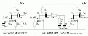
I'm using the original circuit (attached).
I'll try yours and report back.
Btw, can you tell me how you measure Vds (simply stick the probes at the ends of the JFETS)? Also, what simulator are you using?
Thanks a million for your help.
I do not know much the cartridge... sorry! Also, I do not want to turn up the volume
coz it will become too loud. Right now, I have it at about 12 o'clock on the miniwatt.
Guess that means the pre is giving too much gain. The miniwatt will deliver full 2.5W
for 500 mV input.
The circuit you are showing has a lot of differences from the one I am using.
I'm using the original circuit (attached).
I'll try yours and report back.
Btw, can you tell me how you measure Vds (simply stick the probes at the ends of the JFETS)? Also, what simulator are you using?
Thanks a million for your help.
Attachments
Last edited:
So, you don't use the Madk? You use the one in the last pic above? Wait, I think I have it too. CM2000 is the sim. I am pretty sure about the models the betas etc I use for your circuit because I have ironed them out and comppared in practice for the many simplistics. Stay tuned.
CM2000 is the sim. I am pretty sure about the models the betas etc I use for your circuit because I have ironed them out and comppared in practice for the many simplistics. Stay tuned.Salas,
I do not know much the cartridge... sorry! Also, I do not want to turn up the volume
coz it will become too loud. Right now, I have it at about 12 o'clock on the miniwatt.
Guess that means the pre is giving too much gain. The miniwatt will deliver full 2.5W
for 500 mV input.
The circuit you are showing has a lot of differences from the one I am using.
I'm using the original circuit (attached).
I'll try yours and report back.
Btw, can you tell me how you measure Vds (simply stick the probes at the ends of the JFETS)? Also, what simulator are you using?
Thanks a million for your help.
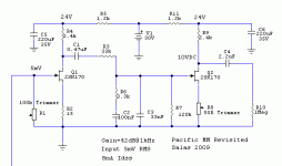
What you got right now is 51.2dB gain and about 1.8VRMS with 5mV average input. Too much for your amp, too much for a non degenerated Njfet second stage regarding THD. The MadK has better Riaa when fed by an accurate reverse Riaa model, yours is ''doctored''. It may be livening up your MM cart though. You must be having 4-5V Vds DC right now with 8mA Idss. Please check. Will see if we can soup up the one you use for your system. More in a while...
Attachments
I'll try yours and report back.
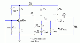
This one is based to what you got. I have used easy, standard values.
Much more compatible gain and output with 8mA Idss and MM, less thd, way to set the Vd to earth DC of your second stage between channels via R8 (also to match ACmV out), along some little Rs degeneration to bring it under control. Stage psu decoupling. Much better Riaa, better it not be doctored as in the original, use your input 100k trmmer load to find your preferable tone with MM carts. Its drastic and handy.
Attachments
Salas,
thanks for all your time!!!!! Really appreciate it.
For some reason, the 9V battery stack had dropped a lot of voltage over the past three four days. They total voltage was at 20 V. With that, the Vds was about 1 V. I put new batteries and now the voltage is at 23.9V.
Vds for one channel reads 4.8V and for the other is 4.9V.
You must be having 4-5V Vds DC right now with 8mA Idss. Please check.
Vds for one channel reads 4.8V and for the other is 4.9V.
So we simulate well, be confident. Tune up to what I have given, its easy with what you got, and let us know. I consumes less battery life too. Next you make yourself a shunt reg.
Salas,
I'm afraid I'll take a day or two to put together what you have shown, with the corrections.
I already soldered the current circuit.
What I need to look for is 10 Vds on the second stage JFET? Is this correct?
Yes, you look for 10VDC from that point I show and ground. If you have one channel still somewhat quiter, you can play with its R8 trimmer until it matches output to the other channel. In that case, the quiter channel may show less than 10VDC after you trim it.
Salas,
Can you help once more?
I got new Nimh batteries.... now I got close to 30V from the battery. How do I drop the 6V?
I want to put a resistor in series with the battery, but I don't know what value unless I know how much current is flowing.
For some reason, I can't measure the current in my existing circuit.
Ohm's law. 1k2 drops 6V for 5mA that each stage will roughly use. 1k-1k2 will get you there depending on your batteries top voltage and how much around 5mA each of your fets really draws in practice. The 220uF caps make a long enough RC time constant with the given resistor ballpark value so to bypass even under 10Hz. Your first stage especially needs that because batteries have enough impedance to pass modulation from the stronger swinging 2nd stage. So you do two good things with one needed Vdrop move.
- Home
- Source & Line
- Analogue Source
- Ultrasimple MM/MC RIAA preamp 2