tschrama said:I had the same feeling... it was a bit bass-light... I cured it by making a proper inverse-RIAA, and adjusting the filter section untill it was within 0.5dB...
Mind sharing your tweaks with us?

What cartridge do you use?
D
sure...from the orgininal Pacific RIAA:
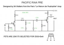
1] moved the coupling cap between stage 1 and two, to just before stage 2..
2] put a resistor parrallel to the resistor to ground in the RIAA filter, to make it 3.09K
3] used a 100nF cap, not 98nF
4] used 2x15nF + 2.2nF + 1nF
chrzz,
Thijs
1] moved the coupling cap between stage 1 and two, to just before stage 2..
2] put a resistor parrallel to the resistor to ground in the RIAA filter, to make it 3.09K
3] used a 100nF cap, not 98nF
4] used 2x15nF + 2.2nF + 1nF
chrzz,
Thijs
Hello Thijs, JohnM, others,
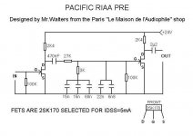
Thijs, is it correct that you refer to the original design as designed by mr. Walters from La Maison de L’Audiophile in Paris as in the attachment? I use this original design already for many years now and feel invited to try this update. Thanks Thijs.
Is it correct that I can read your modifications as follows:
1] moved the coupling cap between stage 1 and two, to just before stage 2. The 470nF is now between the upper node of the 100k resistor and the Gate of the second fet
2] put a resistor parallel to the resistor to ground in the RIAA filter, to make it 3.09K. Is this parallel to the 100k resistor? Then a (composed) value of 3.190 ohm (3k19) would do I guess?
3] used a 100nF cap, not 98nF. This would be instead of the (15n + 15n + 68n )
4] used 2x15nF + 2.2nF + 1nF. Is this instead of the (22n + 6n8) ?
With this modifications it would be interesting to compare this modified original design with the redesign of Thorsten Loesch as applied by Mad K in this thread.
Best, Arjen.
Attachments
HI
the tschrama riaa mod is correct ?
jfet----27k-------------------------470nf--------jfet
................|...........|...........|
...............3k..........33n.......3.09k
..............100n........|...........|
------------------------------------------------gnd--
the point are only for correct image
Thanks
drain----27k-----------------470nf--------jfet
.........................|...........|...........|
.......................3.09k....33n.......100K
......................100n........|...........|
----------------------------------------------gnd--
you have to check the RIAA curve with a inverse-RIAA filter, scope and sine generator.. switch individual capacitors for species of equal value, till you get it right... or start adding 1nF and 470pF values to tweak it..
drain----27k---------------------470nf--------------jfet
.........................|...........|.................|
.......................3.09k....33n.............100K
......................100n........|.................|
----------------------------------------------gnd--
Thanks a lot!!")
.........................|...........|.................|
.......................3.09k....33n.............100K
......................100n........|.................|
----------------------------------------------gnd--
Thanks a lot!!
Wow, this circuit's simplicity is truly appealing. I think I might give it a try. A few questions though:
1) Will measured/matched styroflex capacitors do fine for the RIAA-network? What's your choice?
2) For an MC cartridge with a rated output of 5mV, what output-voltage swing can be expected?
3) How important is the supply voltage of 24V? How about a regulated PSU with CRC + LM338 + C fed from a 25V 30VA toroid?
Thanks for sharing this one,
Dave
1] I use polypropylene. I mixed mathed untill I get a flat transfer function thrue a Inverse-RIAA network. As shown, you can expect about 0.5-to 1.0 dB deviation.
I think polysterene would be the preferred alternative.
2] Each JFET has a gain of about 30dB, that's 60dB in total, but you loose 20dB in the RIAA nrework.. so expect a 1KHz gain of about 40dB, that would mean 5mV in, 500mV out.
I think 500mV would be too high, as the output JFET starts distortion to much beyond 300mV. Maybe you can get rid of some gain to keep the output below 300mV. Exchabnge the first 2.4K resisro with 1.2K, and put another 1.2K in series. This will halve the gain.
3] Power supply must be extremely good. I use 2x 9V NiMh battery with 2200uF and local bypass. I wouldn't dare to use a AC-based power supply. Power supply rejection is allmost non-excistant. Optimum voltage on my build was very low, about 15(?) volt.. 24Volt is too high.
By lowering the voltage, you can effectively cancle the second harmonics of the last JFET stage. Optimum voltage is depended on the Idss of the JFET. I use Idss 9mA, I think...
You can adjust it by carefully look for assymetric distortion of a sine wave, and see at what voltage the assymetry flips.. somewhere in the middle would be close to the optimum.
goodluck,
Thijs
tschrama said:
2] Each JFET has a gain of about 30dB, that's 60dB in total, but you loose 20dB in the RIAA nrework.. so expect a 1KHz gain of about 40dB, that would mean 5mV in, 500mV out.
I think 500mV would be too high, as the output JFET starts distortion to much beyond 300mV. Maybe you can get rid of some gain to keep the output below 300mV. Exchabnge the first 2.4K resisro with 1.2K, and put another 1.2K in series. This will halve the gain.
Sorry, i don't get the part with exchanging the resistors...
tschrama said:
3] Power supply must be extremely good. I use 2x 9V NiMh battery with 2200uF and local bypass. I wouldn't dare to use a AC-based power supply. Power supply rejection is allmost non-excistant. Optimum voltage on my build was very low, about 15(?) volt.. 24Volt is too high.
By lowering the voltage, you can effectively cancle the second harmonics of the last JFET stage. Optimum voltage is depended on the Idss of the JFET. I use Idss 9mA, I think...
You can adjust it by carefully look for assymetric distortion of a sine wave, and see at what voltage the assymetry flips.. somewhere in the middle would be close to the optimum.
goodluck,
Thijs
What about "The Shiny"? http://www.diyaudio.com/forums/showthread.php?postid=1555893#post1555893
With another 10000uF it might work, mightn't it?
I'm sorry to bother you all with this but I built this and for about the first ten to fifteen seconds it worked beautifully but then there was a low, loud rumble and now nothing but the rumble.
I've taken it apart, built it again using new components but to the same result, the only things that are different then the schematic are that I'm using 2SK170GR's (told they'd be a direct drop in) and the ouput cap is an 'lytic. Any ideas would be greatly appreciated.
Thank you,
Steve
I've taken it apart, built it again using new components but to the same result, the only things that are different then the schematic are that I'm using 2SK170GR's (told they'd be a direct drop in) and the ouput cap is an 'lytic. Any ideas would be greatly appreciated.
Thank you,
Steve
Funny! I had not seen this thread until today. But when I saw the schematic, I knew it right away.
I remember when William came up with this circuit, about 20 years ago. Sounded great. There was also a famous tube version (12AX7, IIRC) I built that one with styrex caps. Wonderful sounding preamp.
Never did build the 2SK170 version, but the 2SK170 was used in a lot of simple projects, even mic preamps. Very nice.
Thanks for posting it. Simple can sometimes be so good....
HI panomaniacpanomaniac said:There was also a famous tube version (12AX7, IIRC) I built that one with styrex caps. Wonderful sounding preamp.
Humm.. where I can find ?
HI HawkSpeed I use 2sk170gr matched quads
" The Circuit is speced for 2SK170 with an Idss (selected) of 4-6mA absolute with no more than 0.1mA difference between the two channels (per stage). That is what MUST be used if you want a working phonostage from the discussed circuit without problems."
I have change r 47k to 3k the cartridge loading, big difference .......
nicoch46 said:Humm.. where I can find ?
I don't know, sorry. it's probably somewhere on this very forum, but I didn't see it.
It was basically like the FET circuit in this thread, in fact the FET circuit is probably derived from the tube circuit.
IIRC, it used 1 12AX7 per channel. One 1/2 of the dual triode was used as input with ~40dB gain. Then there was the passive RIAA circuit, then the second triode had another 40dB gain to make up for the passive filter losses. No feedback. But I could be wrong about the gain.
Here is a schematic from our buddies at National Semiconductor with a similar approach. Just using an LM4562 opamp instead.
Attachments
- Home
- Source & Line
- Analogue Source
- Ultrasimple MM/MC RIAA preamp 2