Whether such things would actually decrease distortion would have to be tested in practice. Keep in mind that all the networks used for synthesizing bass are highly nonlinear functions.
While we are at it, the classic compensated two-transistor antilog (or exponential) generator is indeed much easier to get right than the 1 transistor one I was playing around with (to be clear I did this all with a simulator so far).
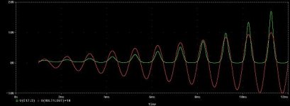
In the enclosed diagram you can see the (augmented) varying input signal from 0.1 to 1 Volts and the respective output signal of the circuit.
Regards
Charles
While we are at it, the classic compensated two-transistor antilog (or exponential) generator is indeed much easier to get right than the 1 transistor one I was playing around with (to be clear I did this all with a simulator so far).
In the enclosed diagram you can see the (augmented) varying input signal from 0.1 to 1 Volts and the respective output signal of the circuit.
Regards
Charles
Attachments
Last edited:
Hi,
One thing to note here is that all you after is low bass roll-off and
enhancement of the fundamentals harmonics, presumably the
more the lower the note with an emphasis on second harmonic
with reducing higher order harmonics.
As mentioned earlier in this thread, probably the best way to
do that at line level is arranging to drive a small transformers
primary into bass saturation at the constant levels before
the volume control. Its easy to arrange a "drive" control
with this arrangement. Also varying some DC current
through the primary as well as the AC will add a lot
more and control the even harmonics at the output.
rgds, sreten.
I already tried boomy box tuning in combination with a capacitor series to the speaker to roll off more fundamental than harmonics. And unloading the amp for signal the speaker can't output is quite helpful for battery run time. Well, the large signal work reduced the x-max problem and the frequency response ended up level, but the effectiveness was insufficient. The only thing the cap did was cut some of the boom and cut most of the treble distortion. What has not changed is that the lowest string is audibly missing from the bass guitar. . .Some things never change it seems.
I remember radio grams with low frequency drivers having non linear suspensions, everything bellow about 100Hz. came out as second harmonic.
rcw
You can of course put a cap in series with a woofer but the result maybe quite different from what you expect. You will have to take the interaction between the capacitor and the driver's impedance into account. Maybe you already did.
The German mag "Hobby HiFi" is using the approach quite often and they once published the design rules they usually apply.
And there was an article by A.N. Thiele in the JAES recently where he showed how to properly dimension series caps. AFAIR he was dealing with closed-box speakers only.
Dependig on how much you want to (or have to) cut off you might be better off by "synthesizing" the series cap by frequency-dependant current feedback. You will loose the impedance transformation effect but you will also relieve the amp from signals that the speaker won't reproduce.
Regards
Charles
Have you seen Maxxbass? Not really DIY but it's supposedly good.
Maxx - Professional Sound for Consumer Electronics
Maxx - Professional Sound for Consumer Electronics
Before: The lowest pitch string of the bass guitar is absent and the three higher pitch strings play with a boomy distortion with only 3 watts till x-max.You can of course put a cap in series with a woofer but the result maybe quite different from what you expect. You will have to take the interaction between the capacitor and the driver's impedance into account. Maybe you already did.
After (4R, 1100u): The lowest pitch string of the bass guitar is still absent but the three higher pitch strings play with a loud clear level response to 10 watts.
This does a useful job, but doesn't really replace the ultrabass circuit.
There's lots of those: Digital Bass Reconstruction ProcessorHave you seen Maxxbass? Not really DIY but it's supposedly good. Maxx - Professional Sound for Consumer Electronics
No idea if that's:
Harmonic divider (DBX120A)
Harmonic even multiplier (distastefully boomy)
Harmonic odd multiplier (Ultrabass)
Putting, "digital" on something is still just marketing hype, what they are doing is to generate second and third harmonics from the frequency content bellow a particular cut off, and then add that to the direct sound.
It is true that you can add a few more wrinkles with digital processing, but I have never seen any reliable research that indicates this is worthwhile, just manufacturers marketing hype.
The various analogue schemes already mentioned are all you really need for a diy device, the other stuff is convenient for manufacturers because they can integrate it very cheaply, but despite all the hype, I very much doubt if is better.
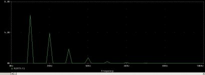
All of the schemes mentioned are much the same in that they essentially multiply the input with a natural anti log function.
As you can see from phase accurate's data, this results in a linear descending series of even and odd harmonics, a full wave rectifier gives the same thing with the odd harmonics missing, and dc saturating a signal saturated transformer gives much the same sort of thing.
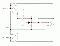
The circuit I am looking at uses a full wave rectifier connected as an integrator, this is basically the circuit I posted with the addition of a capacitor.
rcw
It is true that you can add a few more wrinkles with digital processing, but I have never seen any reliable research that indicates this is worthwhile, just manufacturers marketing hype.
The various analogue schemes already mentioned are all you really need for a diy device, the other stuff is convenient for manufacturers because they can integrate it very cheaply, but despite all the hype, I very much doubt if is better.
All of the schemes mentioned are much the same in that they essentially multiply the input with a natural anti log function.
As you can see from phase accurate's data, this results in a linear descending series of even and odd harmonics, a full wave rectifier gives the same thing with the odd harmonics missing, and dc saturating a signal saturated transformer gives much the same sort of thing.
The circuit I am looking at uses a full wave rectifier connected as an integrator, this is basically the circuit I posted with the addition of a capacitor.
rcw
Me too! However, a schematic from phase_accurate would liven up matters considerably.Hi, I'm completely bored with the OP touting himself
as the arbiter regarding the original question. rgds, sreten.
")
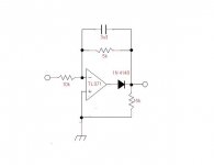
I first tried simulating the classsic circuit like it is shown on page 19 of the following presentation:
http://www.electronics.dit.ie/staff/ypanarin/Lecture Notes/DT021-4/6LogAntiLogAmplifiers.pdf
This one is really hard to get "working" in simulation (getting a good operation point in particular) and taking into account that such things are usually even trickier to get right in practice I tried a variation of the one shown on page 21. This one sets the operation point itself. The prerequisite is that the two transistors are as similar as possible (like two from the same batch or even two out of an array) and that they are thermally coupled.
In order to get it working properly the input has to be biased with a DC voltage as high as the peak voltage of the driving signal. This way it is guaranteed that you never have a negative input voltage. Instead of subtracting the offset at the output I'd suggest to use AC coupling since you would have to get rid of the fundamental frequency anyway (at least to some degree).
Regards
Charles
Well, I have some BC546B and BC546C (and others) and a handy TL082 (and others). The two transistors could either be shrink wrapped together or both of them thermal glued to the op-amp, whichever method looks better to you.
It seems like an additional stereo op-amp is needed for buffer+adder. Is that right?
It seems like an additional stereo op-amp is needed for buffer+adder. Is that right?
- Status
- This old topic is closed. If you want to reopen this topic, contact a moderator using the "Report Post" button.
- Home
- Source & Line
- Analog Line Level
- Ultrabass, psychoacoutstic low bass for little speakers