Hugh Dean, Australias answer to Andy Singer?
For years, Andy Singer, proprietor of Sound by Singer, a hirsute and portly (as if I should talk) legend among NYC audiophiles, in his adds in Stereophile and Absolute Sound, posed discretley behind his massively endowed equipment, Krells, Utopias, Wilson Wamms.... I assume, out of modesty. Rumors were rampant that he wore no pants for these sessions.
Its patently unfair to compare Hugh to the infamous Singer, but the thought of Hugh posing informally with his own equipment....
I'm glad to say that in his new ads, Andy has come out from behind his surrogates, hopefully realizing that folks judge him for his behavior, and not his looks.
As my own son was recently the featured CosmoGirl 'Dream Date of the Month' (I'm soooo proud, but thankfully he get his looks from him Mum), I've been thinking about some vehicle for capitalizing on 'soft core'.
So howzabout a "DiyAudio Hunk of the Month" calendar; Nelson, Hugh, Fred...... all very discrete, naturally.
Special Report From DiyAudio News Service
The news that the iconoclast Mr. Dean, of AKSA fame, is joining the team is truly exciting. His additional efforts to secure funding for the project with that limited edition of his coffee table pictorial, 'Pictures of Hugh', is currently held up by the parochial U.S. Postal Service.
Asked for comment, Mr. Dean responded -
"The 'Man' can't keep me down! I'm still going forward with my crossover album, 'Dead Bug Dance' (Mapleshade). A groundswell of support is arising throughout the world, with AmpAid projects underway in Plano, Texas - 'Haller in the Holler', dobro for the discerning, as well as a Scandanavian Dub album, 'MozFet Breakthru' from Lars C. (with special thanks to Vartina). Rumors are also circulating that an unknown group will also release an album mysteriously titled 'Anglo-Teutonic Current Drive' ".
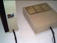
Cheapest enclosure that I managed
two 2x4 mdf board - $12cdn, plus some left overs from prevous projects.
two 2@ 8 foot alum.corner strip - $12.50cdn
so besides screws and paint etc..$24 +25cdn to make two set of these;;
PS, I forgot how much the vent cover cost from Home Depot
Oh , and 16 wooden door knobs for feets @ 1.25cdn each
two 2x4 mdf board - $12cdn, plus some left overs from prevous projects.
two 2@ 8 foot alum.corner strip - $12.50cdn
so besides screws and paint etc..$24 +25cdn to make two set of these;;
PS, I forgot how much the vent cover cost from Home Depot
Oh , and 16 wooden door knobs for feets @ 1.25cdn each
Attachments
I thought the same thing before I read Hugh's thoughts here but my wondering was more about the current direction. What about 100k as "pullup" and active pulldown. What about in slew rate limiting conditions. 100k seems to give not much drive current.AKSA said:2. Can you be absolutely sure that T8, the emitter follower drive to the VAS, is necessary? I tried it and eventually dismissed it as not worth the trouble. However, YMMV, and obviously does, so there must be a reason.......
Peranders: 100k gives more than enough current, at +/- 45V you almost get a full mA to feed the B of the MMBTA42. Even at high slew conditions.
T8 gives a good temperature compensation and removes the Miller effect of the VAS. I think it's worth spending a single transistor on.
")
T8 gives a good temperature compensation and removes the Miller effect of the VAS. I think it's worth spending a single transistor on.
Sorry i said some gibberish above, i meant: Even at high slew conditions there would never be use for more current than that. But maybe the power supply ripple rejection can be improved by replacing the 100k with a 'Current Diode' as suggested in the beginning of this thread.
Lars Clausen said:This thread is continued from 'What is the Gainclone Exactly?'
Ultra Low Cost Amplifier design, here is my first proposal...
Power is 50W in 8 Ohms, 100W in 4 Ohms, 5 - 100.000 Hz.
It is a fairly conventional amplification stage, followed by a industrial MOSFET output (extremely rugged). It can be tweaked and scaled to larger output power with ease....
The values around T5 may have to be experimented with a little.
It should build for less than 10$ including a PCB. (Which i will not be making or selling .. anyone else can do that if they want).
I encourage anyone with ideas for ultra low cost amplifiers to post them here, and let's discuss some solutions.
You can see an enhanced image here: www.lcaudio.dk/ulcamp1.gif
All the best from Lars Clausen
Hi lars... Most interresting.
A second version could be a CFB design .. look at the schematic at the PDF attached.
I think this would be 3 - 5 components more.
Attachments
Sonnya isn't this circuit almost identical to the frontend of The End Mk3 (1995)?
I think the current mirrors you propose (also identical to The End Mk3) can be improved. For optimal performance they would require exact matching. Even if the two transistors in the Gain Stage Mirrors are from the same series they will create the dominating amount of distorsion. There are better ways to go.
But i think maybe you are right a symmetrical design can have less distorsion. I just started off with something that works good every time, and is simple to build. Please post your proposals here, so maybe some DIY'ers out there can have pleasure in building your version of this ULCA clone. (Who said the clone war was over?) btw. you don't have to zip your pdf file, it's almost the same size after zipping.
I think the current mirrors you propose (also identical to The End Mk3) can be improved. For optimal performance they would require exact matching. Even if the two transistors in the Gain Stage Mirrors are from the same series they will create the dominating amount of distorsion. There are better ways to go.
But i think maybe you are right a symmetrical design can have less distorsion. I just started off with something that works good every time, and is simple to build.
Please post your proposals here, so maybe some DIY'ers out there can have pleasure in building your version of this ULCA clone. (Who said the clone war was over?) btw. you don't have to zip your pdf file, it's almost the same size after zipping.Yes, you do! I'll guess you haven't tried to post a pdf yet?Lars Clausen said:btw. you don't have to zip your pdf file, it's almost the same size after zipping.

BTW: To the moderators, webmaster etc, can't you include pdf as an OK file format?

Lars Clausen said:Sonnya isn't this circuit almost identical to the frontend of The End Mk3 (1995)?
I think the current mirrors you propose (also identical to The End Mk3) can be improved. For optimal performance they would require exact matching. Even if the two transistors in the Gain Stage Mirrors are from the same series they will create the dominating amount of distorsion. There are better ways to go.
But i think maybe you are right a symmetrical design can have less distorsion. I just started off with something that works good every time, and is simple to build.
Yes, my thought when i drawed whas that it looked a lot like your frontend from The End MK3.
Yes the currentmirrors can be better, but ... I think when it needed to be a ULCA then i have to do it simple and cheap....
Hi,
That's an interesting design. Like the one from Lars Clausen, I find it interesting not because it seems optimized for low-cost, but because of the topology.
Have you build this one? Do you know how designed it, or where it's from or any other info? I really like it. I have simulated a bit this weekend with this topology, and it has some quirky, quarky issues, but still, it is very differrent and I am trying to design something like this for a while now...
Regards,
Thijs
It would be the perfect solution to a high performance head phone amplifier. I think 5W in 8 Ohms is enough... Even for a sensitive loudspeaker 5W can make enough power for most uses.
Very interesting design. How about using 100 output devices, like this, and producing 50W in 8 Ohms. (With a little bit higher voltage too of course) ??
Very interesting design. How about using 100 output devices, like this, and producing 50W in 8 Ohms. (With a little bit higher voltage too of course) ??
Hi tschrama,
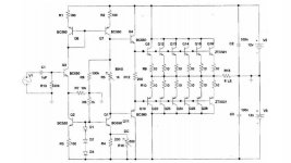
I haven't built the amp (yet) it's really just an idea with components chosen for convenience as much as anything else (no optimisation) but it does simulate quite well and should work ok with a few tweaks, it may need a servo to stabilise DC offset. The cost to build should be very low even including PSU, a pair of surplus 12V SLA batteries would be ideal.
It's essentially a single ended input stage driving a current mirror (Q6,Q7), gain is set by the ratio of R7 and R8. Without the current mirror it would look like a common emitter stage with R7 at one end and R8 at the other. The rest is just standard EF push-pull.
The distortion characteristic is dominated by the input stage and although relatively high compared to amps with nfb it is classic low order so could sound very good coupled to efficient (90dBW+) speakers and the soft-clipping may give the impression that it's more powerful than it really is.
I liked the idea of using multiple small output transistors rather than power transistors because they can be bought very cheaply in quantity, they have higher current gain, bias stability should be good due to the use of high value emitter resistors, the large collective surface area of lots of small devices avoids the need for a heatsink and most importantly rows of transistors look good I specified ZTX's because of their high current rating (500mA) but anything would work providing there are enough of them.
With enough output devices it could be biased into full class-a with a dissipation of less than 25W which could make an interesting and aesthetically impressive project. The problem with building amps is often cost and hardware concerns but by thinking small there's a lot more freedom to experiment with more unusual designs.
I haven't built the amp (yet) it's really just an idea with components chosen for convenience as much as anything else (no optimisation) but it does simulate quite well and should work ok with a few tweaks, it may need a servo to stabilise DC offset. The cost to build should be very low even including PSU, a pair of surplus 12V SLA batteries would be ideal.
It's essentially a single ended input stage driving a current mirror (Q6,Q7), gain is set by the ratio of R7 and R8. Without the current mirror it would look like a common emitter stage with R7 at one end and R8 at the other. The rest is just standard EF push-pull.
The distortion characteristic is dominated by the input stage and although relatively high compared to amps with nfb it is classic low order so could sound very good coupled to efficient (90dBW+) speakers and the soft-clipping may give the impression that it's more powerful than it really is.
I liked the idea of using multiple small output transistors rather than power transistors because they can be bought very cheaply in quantity, they have higher current gain, bias stability should be good due to the use of high value emitter resistors, the large collective surface area of lots of small devices avoids the need for a heatsink and most importantly rows of transistors look good
I specified ZTX's because of their high current rating (500mA) but anything would work providing there are enough of them.With enough output devices it could be biased into full class-a with a dissipation of less than 25W which could make an interesting and aesthetically impressive project. The problem with building amps is often cost and hardware concerns but by thinking small there's a lot more freedom to experiment with more unusual designs.
Richard C,
I love it! My simulation should some serious distortion, but I still like it. I have no doubt that when tweaked a bit it should perform good enough.
If you are serious about building and are ordering parts then (only if you don't mind) maybe you would be willing to oders the parts duoble and send one set to me. Offcourse I will pay your costs.
Regards,
Thijs
Lars Clausen said:It would be the perfect solution to a high performance head phone amplifier. I think 5W in 8 Ohms is enough... Even for a sensitive loudspeaker 5W can make enough power for most uses.
Very interesting design. How about using 100 output devices, like this, and producing 50W in 8 Ohms. (With a little bit higher voltage too of course) ??
Have you seen Dr. Meier's opamp based amplifier? 44 LM6171 per channel, see here.
An externally hosted image should be here but it was not working when we last tested it.
tschrama said:
My simulation should some serious distortion, but I still like it. I have no doubt that when tweaked a bit it should perform good enough.
I think when I simulated the amp I used a single resistor for R4,R16 of around 107 Ohm and a bias resistor of about 460 Ohm for an Iq of 50-100mA. The trickiest part is setting the output to 0V there isn't much room for manouvre with such a low supply voltage but distortion's quite low when everythings set right.
Before ordering parts it's worth building a prototype with just a single pair of O/P transistors so that any issues (and there are a few) can be sorted before commiting to a final design. I'll try and find time to do something this week...
Richard C.
You should try lowering the current of the input transistor, 14 mA is a bit high. I think you will have trouble keeping it DC stable as the temperature of this transistor changes.
With a 100k Gain resistor, you only need 1 mA to produce 100 V of output voltage, more than enough, when you have a 12V supply rail.
And 10mA to feed the current mirror - also way too high 0,2 mA is more than enough.
- Status
- This old topic is closed. If you want to reopen this topic, contact a moderator using the "Report Post" button.
- Home
- Amplifiers
- Solid State
- Ultra Low Cost Amp Design