Wayne,
Just begin by removing the two Rfb resistors on the bad module (unsolder just one lead on each rfb, that's enough)
Then fire it again and measure the voltages across the Jfets drain resistors (1K47 and 1K5)
You should find about 5.2V (and thus a current of 3.5mA).
If not, measure the voltage across the 22R & 47R source resistors and tell us what you find.
If yes, measure the voltages across the 750R current mirror resistors. You should read the same 5.2V voltage
Measure also the cascode bias voltage (between ground and the base of the cascode trannies). It should be near 10V (absolute value)
Tell us what you find.
Best,
Hi Cheff,
So this got really more interesting. I replaced the two precious JFETs and
the amp is doing the same thing. Darn. Jfets dead. It's a disaster.

When I disconnect the feedback, we see that the gate voltages of the new
JFETs are at 0V at both halves. So far so good.
I'm seeing that the voltage across the upper left drain R 1.47k is 1.7V so we
see too little current in that arm of the amp at about 1.1 mA
The other upper drain R has 6.0V across it. So it's at 4.0 mA.
The lower drain R are at 6.4V on the left side and 6.0V on the right side.
Upper source R at 0.203 V left, 0.199 V right.
Lower source R at .097 V left, 0.090 V right.
The trimpot at the X middle is at about middle setting - 25 ohms each way.
THe cascode voltages are correct at 10.43V and -10.47V.
Gotta run now but I'll poke around some more in a couple hours. I'm
suspecting something is bad in the upper left cascode.
Ok Cheff,
I went at it again just now. I think I've found the problem.
I'm seeing that the upper left current mirror BJT has the same emitter and
base voltage more or less which is wrong. THe emitter should be about 0.7V
higher than the base. But when I measure with a voltmeter it does not
indicate a dead short. So I think that BJT is dead rather than a short on
the PCB. On the schematic I have the part designation is Q9.
Now I'm really unhappy because I didn't order any extra parts. I'll scout
around and see if I've got any extra ZTX550 in my parts stash.
I'll post again when I figure out any more.
It was good of you to help out. Disconnecting the feedback was the key
that I needed to be prodded into. I was thinking I'd never get this figured
out with the feedback in there. The things you don't think of....
Quite right, may I sayI'm suspecting something is bad in the upper left cascode.
Considering your measurements on the source resistors, all your Jfets seem OK, 4mA each.
And the older ones were also okay, I guess. Hope you can reuse them later...
The cascode and mirror Vbe measurements were the next step, but you've nailed it down
Just tell us how it goes with a new cascode BJT...
Cheers
Quite right, may I say
Just tell us how it goes with a new cascode BJT...
Cheers
Well, that was it. The outer mirror BJT at the top. I replaced that one and
now I'm able to easily adjust outputs to 1 mV level or less difference and from
ground.
I wonder what caused that to happen. I handle the parts quite well as far
as ESD is concerned and I thought BJTs were quite robust. Oh well.
Now I'll burn it in for a while then readjust and get it into my system. I'm
REALLY looking forward to that. Maybe I'll get to that tomorrow
evening and have a listen. I've been listening to an Aleph P1.7 for a few
years now so I'll see how different this one sounds.
Thanks a lot for the help Cheff and Mod.
Woo Hoo !!!
After first 2 or 3 songs of listening - here's what I think as compared to Aleph P 1.7
clone.
Firstly, the UGS has significantly more gain, I'll have to turn it down a bit.
THe things I notice the most I'd describe as lower noise as I can hear very low sounds
I've never heard before, more detailed, the mids are more lifelike, and I think there
is more bass there also. I'm going to go listen some more.
Anyone else go from AP1.7 -> UGS ? WHat did you think?
Hi Cheff
I got two UGS v3 pcbs and one power supply pcb like http://www.diyaudio.com/forums/attachments/pass-labs/70381d1158327339-ugs-adventures-ugsalim1.gif
can I supply two UGS with only one power supply pcb
I have measured 32 mAc consumption one side of power supply pcb
the consumption of UGS Is +-16 mAdc
can I increase shunt current of the power supply pcb
thx breizheau
Is It necessary (possible) to do modification to power supply board
why at least 10VA transformer - I measure that power board consume only 32 mAc per side with one ugs
I'll take a swag at it... I think I read that the amp is drawing 32 mA at each
of the positive and negative rails. Lets say the PSU on the supply side of the
pass transistor is about 32V, we get .032 * 32 = 1.0 W basically, which for
your setup means about 1 VA bacause your PSU load isn't particularly
capcitive or inductive.
You are well advised to provide a 4:1 ratio of transformer provided : needed.
With that in mind 10 VA is about right for 2 amps.
Keep in mind that the transformer output current is highly pulsed. The
PSU rectifier diodes are forward biased only part of the time.
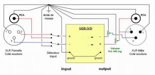
Maybe this could help.
Thanks to the (French) author
I disagree with the schematic.
Specifically, I'd connect pin 1 of the XLR connectors to the CHASSIS ground,
with as short a wire as possible. WHat I do is use a 1 cm (or so) wire
soldered to pin1 of the connector and conected to the mounting screw that
holds the XLR connector to the chassis. This way, the shield of the XLR
connecting cable is drained to chassis ground - which is a low impedance
ground to your building ground.
For the RCA output, you should use an isolated RCA chassis connector, and
connect the amplifier ground to the outer conductor and the pin to the +
output of the amp.
Finally, the amplifier ground is isolated from the chassis ground by a
NTC thermistor - CL60 as a part number comes to mind.
Guess who taught me all this? His initials are NP.
(now I really hope I got it right...
)Sorry for that wayne325, I've posted what I've on hand about UGS project.
You're certainly right for the wiring, secutity first.
The schematic doesn't show if the RCA are isolated or not.
The question was : where stays the pot and which value to use.
UGS is a preamp, not an amp.
You're certainly right for the wiring, secutity first.
The schematic doesn't show if the RCA are isolated or not.
The question was : where stays the pot and which value to use.
UGS is a preamp, not an amp.
Last edited:
Hi Korben, sorry I guess I came on quite tersely at the beginning. Noone has to do
what I say, I was just hoping to help out some perhaps who may use the schematic.
Actually the drain to chassis ground has the advantage of being more safe because its
connected to the chassis. My thinking when I wrote the thing about the XLR pin1
though is that the RF noise gets swamped to the chassis ground rather than the
signal ground, if the signal ground is isolated in some manner. The shorter the wire the
better off you are. I chassis ground the XLR pin1 of the source component, leave the
pin1 of the sink component floating, and connect shield to pin1 of my cables.
- Home
- Amplifiers
- Pass Labs
- UGS adventures