WT said:I plug in my programmer board to the parallel port but not connect to u-controller board yet. (I have to use my dad PC, it is the only one that has parallel port)
Open the ponyprog
Select the AVRmicro, then select the ATmega64
I click on the wrench icon and set parallel port with AVR ISP I/O and select LPT1 then click OK.
I also try probe as Cheff suggest and it said test OK.
At this place you will want to perform the timing calibration
Menu : Setup> calibration
Run calibration? >Yes
Then I go to program options and select Reload files, Erase, Write Program memory (Flash) and Write Data memory (Eprom)
Manu
edit : Sorry CeeVeee you wrote the same ....
...more serious note,
from the previous reply from Cheff: it's true that after using the braid for desoldeing you can be left with a haze of dry solder.
It is good policy to just touch each pin again with the clean tip of the soldering iron just to fuse the dry solder at each pin.
That is enough most times.
The problem arises from the fact that a long cold braid will suck up the excess solder but will also lower the joint temperature and we often get as a result a cold joint.
...no pun intended.
Sorry for that
Best method for desoldering the blown µC while preserving the pcb : use a cutter knife and cut the pins close to the µC case. Proceed gently, to avoid ripping and damaging pcb traces near the corners of the case. You'll need several cutter passes to cut the pins, but take your time. Then use solder braid to remove the pins from the pcb and clean the pcb pads.
If you have a soldering iron with a fine tip - and good eyes and steady hand, you can solder the new µC pin by bin. In fact, I use this method and it works pretty well. It is best to unplug the iron when soldering, to avoid current leakages that could damage the chip. Just replug and let reheat when it gets too cold to solder.
Let us know how it goes.
I just finished soldering up a pair of the UGS boards and a stand alone power supply boards.
I have a couple questions before I hook it all up.
- Do you have to have matched pairs for the MPSA42's or MPSA92's on the power supply board? as I did not match them.
- Do you have to match the ZTX450's & ZTX550's on the UGS boards? as did not match those either.
- Third... I am going to used a PEC carbon pot for the volume control until Twisted Pear Audio released their new Stepped Log Attenuator boards. Will a 50K log pot be fine?
Thanks for the help
Guiness said:I just finished soldering up a pair of the UGS boards and a stand alone power supply boards.
I have a couple questions before I hook it all up.
- Do you have to have matched pairs for the MPSA42's or MPSA92's on the power supply board? as I did not match them.
Nope, no need to match
- Do you have to match the ZTX450's & ZTX550's on the UGS boards? as did not match those either.
Same answer
- Third... I am going to used a PEC carbon pot for the volume control until Twisted Pear Audio released their new Stepped Log Attenuator boards. Will a 50K log pot be fine?
If you use it at input, yes.
Connected to output, I'd rather have a 10K log, but why not, just waiting for the TP pot.
Thanks for the help
Hi...sorry a litle off topic but still on, I think...
is there any one in proces of buying parts for UGS from GB ( preamp, with relay volume conron, dislay...)
I would like to know how much all parts did come out?
where did you buy those parts ?
I have send request for parts from farnell via their representative here in Croatia but it come out at around 450-500 Euro without display !!! I think it's little to much...
at the end how about group buy for the parts
No hard feelings, that GB was more than a year agoyoke said:Thanks Maousse for replay.
Unfortinaly I miss this GB on franch forum, didn't know that there was one ;-)
I will have to find some cheap place, probable in USA because of USD/EURO diference.
Debugging display 2
Hi guys,
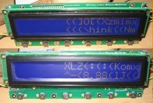
Built display type 2, flashed it ( 3 times ) after initial tests but....
it's looks to me as if my data is reaching the display but it's junk!
I checked the processor, solder looks good.
The actions look ok, display changes when i sellect different inputs, it even responds to the encoder and sets the led flashing, waiting to memorize new values.
but it's all junk in the crystalfonts...and only the right half of the display gets data.
When system comes up the first picture ( hello message ) comes up ...then after a while the second pictures displays....as i say motions are ok...but display is junk.
any help from you UGS pros would be welcome.
Hi guys,
Built display type 2, flashed it ( 3 times ) after initial tests but....
it's looks to me as if my data is reaching the display but it's junk!
I checked the processor, solder looks good.
The actions look ok, display changes when i sellect different inputs, it even responds to the encoder and sets the led flashing, waiting to memorize new values.
but it's all junk in the crystalfonts...and only the right half of the display gets data.
When system comes up the first picture ( hello message ) comes up ...then after a while the second pictures displays....as i say motions are ok...but display is junk.
any help from you UGS pros would be welcome.
Attachments
Hi CeeVee,
You're the first one who's getting so weird messages
You've flashed the right software version ?
I recently debugged a board from the same GB as yours, and it worked perfectly with this display, so the layout doesn't seem to be the cause...
What is the exact reference of the display ?
Sorry for that mess
Hi Cheff,
Yes the software is the right one.
The display i'm using for this one is:CFAH2002L-TMI-ET
...but i'm guessing i might have connected it to the wrong socket.
The Vincent GB buy board i'm using has a socket at left side ( the one i used )for "100mmx40mm LCD" and this display is much bigger .
The other , top, socket is for a 146x43 connector....????
I'm beggining to suspect i used the socket that is for the optrex.
I don't have the pdf showing the connection of the Crystalfontz to this board.
I suppose you've not forgotten to flash the eeprom too...
It puzzles me quite a lot, and I've got to give it a thought...
Sorry for inconvenience...
Could you test your display on the other version (the slim one) ? It requires an adaptator for correct pinning, and the backlight will be faint (or you can omit the backlight, simply shifting the connector by one row), and flash the correct software.
- Home
- Amplifiers
- Pass Labs
- UGS adventures