Double isolation
hmm... does that mean that the safety earth is left floating? Or is the power supply ground connected to the safety earth?
I am not clear on double isolation. Sorry for this basic question as I googled this and there's some generic description on double isolation, but I want to be very clear on this as this is a safety issue. From the description that i have read, my understanding is the power supply ground and the signal ground is left 'floating' with reference to the safety earth. Now, if this is for commercial equipment, that is fine. But, for DIY amps, there's probably a higher chance of a live wire becoming unattached (poor soldering, etc) and may touch the chassis. Isn't this a safety issue?
Thanks for your input on this.
double isolation
actually double isolation requires the use of coupling capacitors on the mains, this is no longer a valid means of isolation as the capacitors radiate imf, the chances are that you may even connect your amp to a peice of equipment that is earthed to chassis anyway! I read somewhere about connecting the power/speaker ground to chassis and earth to chassis with a .22uf capacitor and a 100r resistor in paralell, then the signal ground is tied to the chassis as far away from the power ground as possible.
hope it helps .....
TAWN!
"actually double isolation requires the use of coupling capacitors on the mains, this is no longer a valid means of isolation ..."
I'm not quite sure what you mean, but all commercially sold equipment with 2-prong connectors, and that's the large majority, is built with double isolation. It must be, because with a 2-prong line cord, mains ground is not available. All RCA-cinch are then connected to chassis and so is signal ground.
Of course, the double isolation task is simplified if you use a plastic housing (e.g, in a kitchen radio).
Javin5 said:"actually double isolation requires the use of coupling capacitors on the mains, this is no longer a valid means of isolation ..."
I'm not quite sure what you mean, but all commercially sold equipment with 2-prong connectors, and that's the large majority, is built with double isolation. It must be, because with a 2-prong line cord, mains ground is not available. All RCA-cinch are then connected to chassis and so is signal ground.
Of course, the double isolation task is simplified if you use a plastic housing (e.g, in a kitchen radio).
I think you are referring to European countries. Commercial equipment are sold with 3-prong connectors in some countries. If you check the equipment with 2-prong line cord, there's 'almost' always an external ground node on the chassis where you can link the ground to the housing mains.....
Anyway, after reading some of Bruno's notes on this, my understanding is that for the ideal case, the chassis should be grounded to the mains earth. This works well for XLR connectors, but may cause ground loop issues if RCA connectors are used. Hence, the chassis should be 'floated' if RCA connectors are used.
I am wondering whether a ground lift scheme will achieve the same thing.........
"I think you are referring to European countries ..."
Yes, mostly. I'm aware that rules vary in different regions of the world. It is interesting to look at the schematics in an international edition of a service manual for a Denon, HK, or other brand amplifier. The changes for the different regions are indeed mainly in the grounding and the power line input section.
Yes, mostly. I'm aware that rules vary in different regions of the world. It is interesting to look at the schematics in an international edition of a service manual for a Denon, HK, or other brand amplifier. The changes for the different regions are indeed mainly in the grounding and the power line input section.
Replacing capacitors
I'm planning to replace all the elcap on the ucd400 with better types ( i.e. lower esr ).
I know that the 470mF caps can be replaced adding a 10mF caps in parallel.
There are some other beware to replace the rest of elcaps ( and also the 680 nF mkt ) ?
Thanks.
I'm planning to replace all the elcap on the ucd400 with better types ( i.e. lower esr ).
I know that the 470mF caps can be replaced adding a 10mF caps in parallel.
There are some other beware to replace the rest of elcaps ( and also the 680 nF mkt ) ?
Thanks.
Re: Replacing capacitors
Just as a tiny pedantic point, you probably mean uF for microFarad; mF stands for milliFarads. Studly a designer as Bruno may be, I rather doubt he found a way of stuffing a couple of half-farad caps onto the UcD.
There is a way of doing it with a capacitance multiplier, but efficiency would go out the window. Or would it be that bad? Hmmmmm.
cld1354 said:I'm planning to replace all the elcap on the ucd400 with better types ( i.e. lower esr ).
I know that the 470mF caps can be replaced adding a 10mF caps in parallel.
There are some other beware to replace the rest of elcaps ( and also the 680 nF mkt ) ?
Just as a tiny pedantic point, you probably mean uF for microFarad; mF stands for milliFarads. Studly a designer as Bruno may be, I rather doubt he found a way of stuffing a couple of half-farad caps onto the UcD.
There is a way of doing it with a capacitance multiplier, but efficiency would go out the window. Or would it be that bad? Hmmmmm.
Re: Re: Replacing capacitors
Obviously I mean microFarad.
' Just as tiny pedantic point' : μF ( not uF ) is for microFarad.
Anyway, someone knows the brand of the 470μF caps on the UcD400?
On mine there is no brand reported but it seems a Panasonic CE.
To BWRX :
Not particulary reason for modification, but you know the tweaking fever ....
DSP_Geek said:
Just as a tiny pedantic point, you probably mean uF for microFarad; mF stands for milliFarads. Studly a designer as Bruno may be, I rather doubt he found a way of stuffing a couple of half-farad caps onto the UcD.
There is a way of doing it with a capacitance multiplier, but efficiency would go out the window. Or would it be that bad? Hmmmmm.
Obviously I mean microFarad.
' Just as tiny pedantic point' : μF ( not uF ) is for microFarad.
Anyway, someone knows the brand of the 470μF caps on the UcD400?
On mine there is no brand reported but it seems a Panasonic CE.
To BWRX :
Not particulary reason for modification, but you know the tweaking fever ....
Hi,
Rubycon ZL 470"uF" /100V fits nicelly there")
I consider a gyrator just for the input opamp PS
Rubycon ZL 470"uF" /100V fits nicelly there
There is a way of doing it with a capacitance multiplier, but efficiency would go out the window.
I consider a gyrator just for the input opamp PS
Grounding clarifications - UCD400hg
Just finished up my UCD400hg today. Slight hiss on my speakers - audible only when i put my ears about 3 inches from the woofer. Any idea what's the problem?
Currently, I am not using the hypex grounding scheme as I am not very clear on the overall schema - I am basically using a star ground to the chassis, and using a ground uplift (2 ohm) connected to the mains earth. This it with RCA inputs
Now, I am thinking of redoing it according to the hypex scheme, and would like some confirmation on my understanding. According to the documentation, and my interpretation of the circuit diagrams, I need to:
1. Connect the chassis to the RCA ground (if I am using insulated RCA) and this will go to the signal ground on the board. If my interpretation is correct, that means that the chassis is connected at two points (on a stereo amp), one to each board. THis means that the signal ground is left floating?
2. I am not clear on the power supply ground. Do I connect the power supply ground (from the transformer secondaries) to the main's earth, or do I leave it floating? The diagram on the data sheet seems to show that it is connected to the main's earth. Can someone help clarify on this?
THanks!!!
Re: Grounding clarifications - UCD400hg
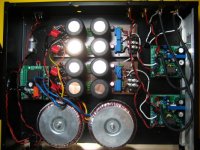
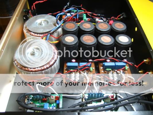
Fixed the problem. Left both power and supply ground floating. Dead silence. I am very happy with my setup now. Still running it in, but I am getting great detail, very very good treble and my bass is coming back.... Extremely happy with it. Only problem is that it gets a bit hot in the enclosed space where I put my amp - I need to figure that out. the heat sinking is pretty minimal at the moment, just a sheet of aluminium added to the inside of the chassis. Here are the pics:
Specs:
UCD400hg at 53V rails.
Dual mono 330VA Nuvoterm tranformers
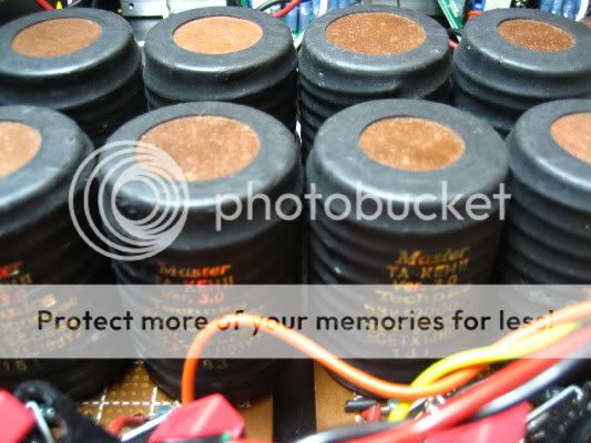
40000 microfards per channel, using Technics TakeII Bamboo Capacitors...
Hypex softstart.
alvinlim said:Just finished up my UCD400hg today. Slight hiss on my speakers - audible only when i put my ears about 3 inches from the woofer. Any idea what's the problem?
Currently, I am not using the hypex grounding scheme as I am not very clear on the overall schema - I am basically using a star ground to the chassis, and using a ground uplift (2 ohm) connected to the mains earth. This it with RCA inputs
Now, I am thinking of redoing it according to the hypex scheme, and would like some confirmation on my understanding. According to the documentation, and my interpretation of the circuit diagrams, I need to:
1. Connect the chassis to the RCA ground (if I am using insulated RCA) and this will go to the signal ground on the board. If my interpretation is correct, that means that the chassis is connected at two points (on a stereo amp), one to each board. THis means that the signal ground is left floating?
2. I am not clear on the power supply ground. Do I connect the power supply ground (from the transformer secondaries) to the main's earth, or do I leave it floating? The diagram on the data sheet seems to show that it is connected to the main's earth. Can someone help clarify on this?
THanks!!!
Fixed the problem. Left both power and supply ground floating. Dead silence. I am very happy with my setup now. Still running it in, but I am getting great detail, very very good treble and my bass is coming back.... Extremely happy with it. Only problem is that it gets a bit hot in the enclosed space where I put my amp - I need to figure that out. the heat sinking is pretty minimal at the moment, just a sheet of aluminium added to the inside of the chassis. Here are the pics:
Specs:
UCD400hg at 53V rails.
Dual mono 330VA Nuvoterm tranformers
40000 microfards per channel, using Technics TakeII Bamboo Capacitors...
Hypex softstart.
Attachments
Does your box have ventilation holes up and down?
In my monoblocks I placed the modules vertically and made holes on the box to increase convective heat remotion. I noticed that the module that has the output coil downwards gets hotter than the one that has it upwards. I had to install an external heatsink to it (61VDC power rails)
Good luck,
M
In my monoblocks I placed the modules vertically and made holes on the box to increase convective heat remotion. I noticed that the module that has the output coil downwards gets hotter than the one that has it upwards. I had to install an external heatsink to it (61VDC power rails)
Good luck,
M
heat...
Hi it doesn't really heat up when i put in in open space. It just get warmish. I think the issue is that I am putting the amp in a cabinet. May need to get some forced ventilation for the cabinet.
maxlorenz said:Does your box have ventilation holes up and down?
In my monoblocks I placed the modules vertically and made holes on the box to increase convective heat remotion. I noticed that the module that has the output coil downwards gets hotter than the one that has it upwards. I had to install an external heatsink to it (61VDC power rails)
Good luck,
M
Hi
it doesn't really heat up when i put in in open space. It just get warmish. I think the issue is that I am putting the amp in a cabinet. May need to get some forced ventilation for the cabinet.
One module burned up...
After comming back from a trip to see friends, I tried to turn on my amp and one of the modules wouldn't turn on... Replaced both fuses, turned it back on and they immediately blew. On closer inspection, the area around the coil was burned up a little, so I'm guessing it's fried. I had a friend staying at my place, who may have done something, but I really don't know what happend. I'm betting on either our horrible ConEd electricity or user error...
Does anyone know what might have caused this?
Anyway, I was planning on eventually adding 2 more channels and actively biamping (my PSU and 1450VA transformer should easily handle 4 units)- this just gives me motivation to place an order with Hypex sooner...
So, will the current ST UcD 400's match my remaining channel?
I was thinking about using the HG for the high end (From ~800Hz up) and the ST for the bottom. Would it be better to stay with the ST all around to keep the sound the same?
Since I am planning on using a DCX, I will need some sort of volume control after the crossover... would it be better to use pots to passively attenuate the signal after the DCX or would it be better to connect a pot with ajumper to RG on the modules and adjust the gain there?
http://www.hypex.nl/docs/gainappnote.pdf
Reading through this again, I think it would probably be best not to adjust the gain... because the input would no longer be differential, at 0db gain at the buffer stage, Right?
And what happened to the US Dollar? ...these exchange rates are killing me.
transformer noise
Hello All,
I recently built an amp with TR501/SupplyHG/UCD400HG.HxR. Soundwise, I'm very satisfied.
However, when finishing the chassis, I noticed, that the transformers are making some generating hum. This was not really disturbing when the chassis cover is removed, but I guess this is amplified if the cover is in place.
Although I do not feel vibration if touching the transformers, it definitely seems that they're making the noise.
I checked for DC on power the line, but the multimeter did not show anything.
Any hints solving this problem?
Thanks,
igy
Re: transformer noise
This will sound odd, but put a cloth on the chassis cover then a couple of heavy items such as bricks. If the noise is reduced, it's likely the chassis, especially if it's magnetic material like steel, could be reacting to the field around the transformer.
Something like this might help:
http://www.partsexpress.com/pe/showdetl.cfm?&Partnumber=268-010
You don't have to get this all the way from the States, as car audio places in Europe are very likely to carry something of the sort.
igy137 said:Hello All,
I recently built an amp with TR501/SupplyHG/UCD400HG.HxR. Soundwise, I'm very satisfied.
However, when finishing the chassis, I noticed, that the transformers are making some generating hum. This was not really disturbing when the chassis cover is removed, but I guess this is amplified if the cover is in place.
Although I do not feel vibration if touching the transformers, it definitely seems that they're making the noise.
I checked for DC on power the line, but the multimeter did not show anything.
Any hints solving this problem?
Thanks,
igy
This will sound odd, but put a cloth on the chassis cover then a couple of heavy items such as bricks. If the noise is reduced, it's likely the chassis, especially if it's magnetic material like steel, could be reacting to the field around the transformer.
Something like this might help:
http://www.partsexpress.com/pe/showdetl.cfm?&Partnumber=268-010
You don't have to get this all the way from the States, as car audio places in Europe are very likely to carry something of the sort.
Re: Re: transformer noise
Thanks for the help! It's a standard 19" rack chassis, front and back plate is alu, the rest is steel.
I experimented a bit trying to push each side with my hands, it makes a small improvement, but still far from the open top version.
It's quite interesting, because otherwise the chassis is much more rigid with the cover on.
I'll play with it, but probably it's time to build a chassis using those 4mm thick alu sheets I have in the workshop (I wanted to avoid that, that's why I bough the rack).
DSP_Geek said:
This will sound odd, but put a cloth on the chassis cover then a couple of heavy items such as bricks. If the noise is reduced, it's likely the chassis, especially if it's magnetic material like steel, could be reacting to the field around the transformer.
Something like this might help:
http://www.partsexpress.com/pe/showdetl.cfm?&Partnumber=268-010
You don't have to get this all the way from the States, as car audio places in Europe are very likely to carry something of the sort.
Thanks for the help! It's a standard 19" rack chassis, front and back plate is alu, the rest is steel.
I experimented a bit trying to push each side with my hands, it makes a small improvement, but still far from the open top version.
It's quite interesting, because otherwise the chassis is much more rigid with the cover on.
I'll play with it, but probably it's time to build a chassis using those 4mm thick alu sheets I have in the workshop (I wanted to avoid that, that's why I bough the rack).
- Home
- Amplifiers
- Class D
- UcD400 Q & A