I'm pretty sure their "optimized" ic is just a rebadged IRS20124 or similar gate driver.
We'll find out as i have ordered one of the smallest Anaview amplifiers from profusionplc.com
It is possible that they have actually crammed their entire circuit, comparator, gate drive, the integrator and all into that one ic they mention.
We'll find out as i have ordered one of the smallest Anaview amplifiers from profusionplc.com
It is possible that they have actually crammed their entire circuit, comparator, gate drive, the integrator and all into that one ic they mention.
Wont simulation just give ideal readings? I feel this amplifier gives totally different results on board. as the board layout , routing and component placement matters a lot. And also the way switching noise is feed back .
I had same basic circuit with different layouts . one is a piece of s*h*i*t. and other is as smooth and clean as this is just the one. and the only difference is layout.
I had same basic circuit with different layouts . one is a piece of s*h*i*t. and other is as smooth and clean as this is just the one. and the only difference is layout.
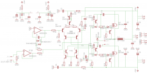
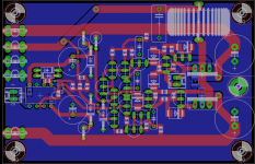
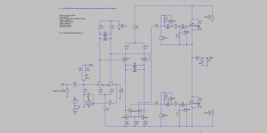
Use IC1B as inverting amp with 20K resistor as input and 20k resistor as feedback. This preserves the "zero common mode" overall topology. This also allows changing the preamp gain.I'm turning that simulation into an actual board layout, and adding a input buffer to bring input impedance back up to around 20k or thereabouts:
Try adding a cascode, so you can compare the subjective result, with and without cascode.
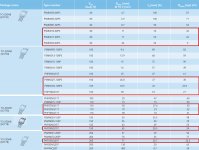
See attached table for the Philips-NXP MOSFETs.
Attachments
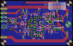
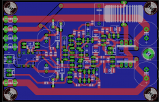
Very nice design. On paper, the performance/complexity ratio looks impressive. Please note I could not reproduce the very low THD figure of the Anaview application, on simulation. All I get is a THD figure divided by 2, at 5 kHz. In search for more performance, I've tried adding bells and whistles like a cascode, a NFET differential input stage, etc. On simulation it appears that THD still could get lowered by adding a NFET input stage. See attached figures.The board has been finalized and and order to seedstudio has been made. In about 30 days we'll find out if this is gonna work at all what so ever.
Attachments
Last edited:
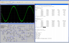
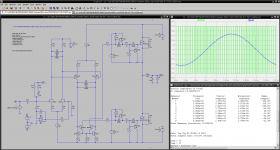
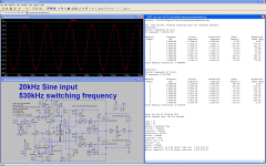
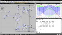
Note that i used 1kHz, i tried running a sim at 20kHz and just as usual THD has risen to 0.1% THD.
But thats because simulation also takes the ripple into account as harmonics wheres in the real world THD measuring gear only measures the harmonics of the fundamental and ignores ripple.
But thats because simulation also takes the ripple into account as harmonics wheres in the real world THD measuring gear only measures the harmonics of the fundamental and ignores ripple.
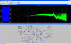
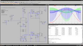
The cross-conduction spikes look worrying. See attached picture. No power supply/decoupling caps can survive this in the long run. We need to adjust the MOSFETs overlap, so the cross-conduction spikes remain below 5 amp or so.
Attachments

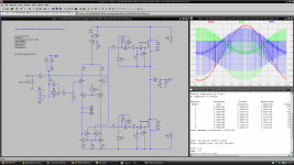
Hello Tekko, I just tried reproducing your UcD simulations. Actually, I doubt they reflect the real world behaviour, with cross-conduction current spikes reaching 25 Amps or so. Anyway, the Anaview feedback seem to improve distortion. Adding two schottky diodes as limiter in the collectors of the input stage seem to reduce the cross-conduction spikes, at the cost of a heavy distortion penalty.
Attachments
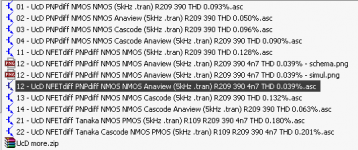
-
 Tekko - UcD PNPdiff NMOS NMOS Cascode Anaview (5kHz .tran) R8 265 THD 0.046%.png117.6 KB · Views: 550
 -
 Tekko - UcD PNPdiff NMOS NMOS Cascode (5kHz .tran) R8 265 THD 0.093%.png116.7 KB · Views: 504
 -
 Tekko - UcD PNPdiff NMOS NMOS Cascode (5kHz .tran) R8 265 THD 0.232% (schottky limiter ON).png114.7 KB · Views: 231
 -
Tekko - UcD simulations.zip496 KB · Views: 181
Yes indeed. I'm impatient. In the meantime simulation helps tweaking the components values for maintaining cross-conduction under control. I guess THD will be dictated by this. In the real world, how do you measure cross-conduction, apart from the intensity of the pain you get on your finger when touching the MOSFETs? Do you insert a 0.1 Ohm resistor, and watch the voltage drop using a battery operated 100 MHz oscilloscope (batteries for isolation)? Or, do you isolate using a transformer, able to pass the DC without entering saturation, only transferring the AC spikes to the secondaty? Any idea welcome.We'll see in about 30 days.
Determined by how hot the fets get, slightly warm with just a piece of aluminum = borderline correct/too little deadtime setting. (most class d with a ability to be mounted to a bigger heatsink)
Stone cold with little or no heatsink but still decent/good sound = borderline correct/too much deadtime but low enough to still be listenable. (most class d that rely on the board groundplane alone for heatsinking)
Stone cold and bad sound = way way way too much deadtime, sound gets a breaking glass kinda tinge to it and feels generally harch. (most cheap class d)
Aren't there schemes monitoring the cross-conduction, automatically adjusting it? I'm going to investigate the dual stage UcD, the one featuring a dual NFET as input differential stage, followed by a dual PNP differential stage. Perhaps, varying the PNP differential bias current (I2) and/or varying R209 would provide some cross-conduction control.
Attachments

Last edited:
Im trying out something i have never tried before, measuring the current across the output filter inductor, integrating it and feeding the signal back together with the error feedback from the anaview circuit.
It doesent seem to affect THD much, but it does seem to reduce the change in switching frequency slightly, because it generates a second error signal correcting for the change in inductor slewrate, atleast i think thats what happens.
It doesent seem to affect THD much, but it does seem to reduce the change in switching frequency slightly, because it generates a second error signal correcting for the change in inductor slewrate, atleast i think thats what happens.
- Status
- This old topic is closed. If you want to reopen this topic, contact a moderator using the "Report Post" button.
- Home
- Amplifiers
- Class D
- UcD Philips UM10155 LTspice simulation