
Decreasing inductance increases the point(in Amps) where abnormal distorsion and noise begins.With 10uH that zone is near clipping at 18kz and 2 ohm load.With 1 ohm load and 15khz,18khz and beyond i still have problems and I do not want to decrease inductance any further.
distorsion begins here far beyond clipping level - 18khz 1 ohm load.
distorsion begins here far beyond clipping level - 15khz 1 ohm load.
distorsion begins here at clipping level for 18khz 2 ohm load
no distorsion at clipping level for 18khz 4 ohm load
So..as load impedance decreases and frequency increases heavy distorsion(white noise and lower frequency sounds) apear bofore clipping level..why?
distorsion begins here far beyond clipping level - 18khz 1 ohm load.
An externally hosted image should be here but it was not working when we last tested it.
distorsion begins here far beyond clipping level - 15khz 1 ohm load.
An externally hosted image should be here but it was not working when we last tested it.
distorsion begins here at clipping level for 18khz 2 ohm load
An externally hosted image should be here but it was not working when we last tested it.
no distorsion at clipping level for 18khz 4 ohm load
An externally hosted image should be here but it was not working when we last tested it.
So..as load impedance decreases and frequency increases heavy distorsion(white noise and lower frequency sounds) apear bofore clipping level..why?
Last edited:
Where exactly are these waveforms taken? Can you do an FFT?Question:
Do you think changing lm311 with lt1016 will decrease distorsions?
It has 10ns response time.
Question:
Do you think changing lm311 with lt1016 will decrease distorsions?
It has 10ns response time.
I use the TL3016 (lower cost from TI) version of this chip with great success in full-bridge designs. The LM311 is certainly a bit on the slow side. The TL3016 needs +/-5V supplies though, as it won't tolerate +/-12V rails. Check the data sheet before using it!
Promised FFT:
No load:
8A load 1 ohm way before clipping level
No load:
An externally hosted image should be here but it was not working when we last tested it.
8A load 1 ohm way before clipping level
An externally hosted image should be here but it was not working when we last tested it.
anything from schematic level of change, maybe only some parts change... and can be the PCB... higher the freq. more important pcb is and components too, slow, 20years old components really don't work good with higher freq.
residual is not a problem, that is normal for this type of amp, but "residual" on residual is not something you would expect to be there, should be pure sine . what is your cutoff freq. of output filter?
residual is not a problem, that is normal for this type of amp, but "residual" on residual is not something you would expect to be there, should be pure sine . what is your cutoff freq. of output filter?
Residual is almost pure sine...the image has the 18khz signal on it..
I am sorry but i need more specific advice if you can give it to me..please read the last 3-10 pages for aditional information if you can.
I am gratefull for any ideea you may have.
Are you running the LM311 from +-3V or from +-12V?
lorylaci: +-6.5 V since i am using gain 10x..but the problem is the same with +-3 volts
luka: yes..those tests were with 18khz input signal..
Distorsion starting point is only influenced by output inductance.
-more inductance:distorsion starts at lower current.
-less inductance:distorsion starts at higher current.
luka: yes..those tests were with 18khz input signal..
Distorsion starting point is only influenced by output inductance.
-more inductance:distorsion starts at lower current.
-less inductance:distorsion starts at higher current.
Last edited:
lorylaci: +-6.5 V since i am using gain 10x..but the problem is the same with +-3 volts
luka: yes..those tests were with 18khz input signal..
Distorsion starting point is only influenced by output inductance.
-more inductance:distorsion starts at lower current.
-less inductance:distorsion starts at higher current.
You should not operate the LM311 over +-5 V, since 2N5904 can only take 5V at base safely. Higher voltage will make the LM311 operate slower, since higher voltage swing it will need to produce.
The output LC filter should be calculated for the load impedance. This is especially true for signal near to corner frequency. The UcD setup helps you getting down peaks and dips near corner frequency, but at the cost of phase responses etc... which will shrink your modulation limit.
Since this is a Class-D amplifier it cannot be controlled up to voltage rails, because modulation error starts at the 70-90% of the voltage rail. It depends on propagartion delay, whether you can take it up to 70 or 90%. If you change the LM311 to a much faster comparator, you will spare a lot of prop delay. Changing IR2110 ot IR2010, and making a faster level shift will decrease prop delay too. If you lower the switching frequency by changing feedback you can increase modulation limit too (but at the expense of higher switching residual).
Ok..thanks lorylaci for those details.
So it is normal for the original circuit to not work in 1 ohm load /high current and frequency.
I will try changing lm311 to lm319 or lt1016 and see what happens.
Ir2010 is only available here in smd package....
The original 30uH, 1,5uF is for 4 Ohm load, for 1 Ohm load the recalculated filter values are 7,5uH and 7,5uF (for 30kHz corner freq, a good compromise). So it is normal that for that load you need lower inductance value.
Change the switching frequency from 360kHz to about 250kHz. Then you can get out more power.
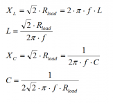
Attached you will find formulas for butterworth filter calculation.
Attachments
- Home
- Amplifiers
- Class D
- UCD 25 watts to 1200 watts using 2 mosfets