I think that oscillatory circuit is good, amp dont oscilatte when music is dont played and start to osilte and continue with or without input signal.
Main problem is input part maybe feedback or gain. Maybe lacis schematic is beter because he use different values of input components and lower gain, normal conection of comparator.
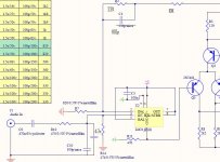
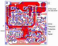
- On first picture is main schematic but I increased swich.freq. to 250KHz. Gain is 47x.Now I use that curcuit
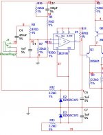
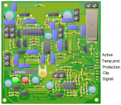
- On second picture is lacis schematic with lower gain and other changes that I have already mentioned in the previous sentence
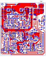
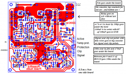
- On third picture is my new pcb with lacis schematic and very soon I will try it.
PCB is very small 8x7cm but its has protection and i plan to use by pass diode mur120 with slower fets like IRFP250N. Its allright that? Becasue this schematic is for 330KHz.
I think this schematic and board can resulve noise problem, what do you think?
Thank you
Main problem is input part maybe feedback or gain. Maybe lacis schematic is beter because he use different values of input components and lower gain, normal conection of comparator.
- On first picture is main schematic but I increased swich.freq. to 250KHz. Gain is 47x.Now I use that curcuit
- On second picture is lacis schematic with lower gain and other changes that I have already mentioned in the previous sentence
- On third picture is my new pcb with lacis schematic and very soon I will try it.
PCB is very small 8x7cm but its has protection and i plan to use by pass diode mur120 with slower fets like IRFP250N. Its allright that? Becasue this schematic is for 330KHz.
I think this schematic and board can resulve noise problem, what do you think?
Thank you
Attachments
Nikola!
Power line = 230 V AC 50 Hz, and the most important part is earth connection. What is earthed and what is not?
You said you have volume potmeter, but I don't see where. And if there is potmeter, then the question is still: what happens to the noise if potmeter is on maximum (quantitative, if it's possible)?
If noise disappears on max., then the noise comes in capacitive (=shielding is not good enough).
Last edited:
I don't understand.Main problem is input part maybe feedback or gain.
PCB is very small 8x7cm but its has protection and i plan to use by pass diode mur120 with slower fets like IRFP250N. Its allright that? Becasue this schematic is for 330KHz.
I don't see any reason to use bypass diode (this way).
I think this schematic and board can resulve noise problem, what do you think?
I would be very surprised! Based on your informations I can tell the noise is not caused by the amplifier. But the distorted high is.
Please state: is there volume potentiometer now or not? General rule: all test results can be understood correctly only if we know the circumstances!
This is a big step ahead! Is this permanent? I mean: after you turned up the volume (with music), and turned down again, does the noise remain, or disappears?
Does the amp continuously work after it started to work?
Do you mean there is 1 second clean music output, and then noise appears, or there is nothing on output for 1 sec, and then the noise and music appears together?
The first case is hard to be explained, but the second one is easy: the amp is always noisy, but it simply doesn't work, doesn't oscillate in the first second.
In all tests you shold make shure the amplifier does work! If you don't have a scope (which is a very unfortunate state), then the supply current can indicate the operation. You must have a multimeter at least!
This is a very important information, and this already told what the source of noise is: power line. We only have to search for the penetration point and mode!
What is the music source? Write (even better if you draw) everything what is connected directly or indirectly to the amplifier! Even if it is switched off! Power supplies too!
And back to a previous test: what if you short input? (1: with all things still connected!, 2: make shure amp is still working!)
Shorting input should be tested on both ends of the input cable!
This is a different error. One thing at once!
EE ferrites can not be very bad, only if there is not enough air gap. (Or if cores are very small.) Number of turns should be more than 10 (preferably 20), gap should be more than 1-2 mm (depending on max. power), and wire over the gap should be avoided. Half turn also should be avoided!
Why don't you tell the dimensions of your core and the approximate number of turns? More info cant hurt! BTW: supply voltage and load impedance can be also interesting! BTW: is it stereo or single channel? The more info you tell the more hints you can get!
(Maybe you've told these things earlyer, but 1: nobody remembers everything, 2: things can change.)
If the amp has no negative feedback then any power supply noise will modulate the output. I had the same problem with one of my early designs.
I managed to reduce the hum with a DC offset pot on the input which gave a small offset to the input signal. I tuned the pot to find a sweet spot.
Pafi!
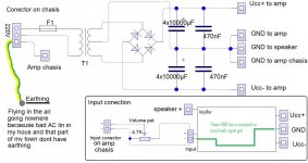
- My house and that part of my town dont have earthing. That is horrible i know but what can i do about it, nothing.
On AC power cable I have earth and earth is conected to amplifier chasis. After transformer "BIG" GND (medium extract from transformer) is conected to capacitors, speakers and amplifier and to amp chasis to.
Signal gnd is conected to volume pot and amp, but on the pcb board signal gnd is same line as power GND.
- Volume pot is beetwen active crossover and amplifier board, on signal cable.
- When volume pot is on minimum i dont have a noise, but how i volume up, noise in speaker is louder and when pot is on max I have a noise too but its not loud, its very little but there is noise and sound is like fingers on signal cable. I have impression that i have problem with gnd, somethin like that.
Picture is more valuable, more then thousand words.")
- My house and that part of my town dont have earthing. That is horrible i know but what can i do about it, nothing.
On AC power cable I have earth and earth is conected to amplifier chasis. After transformer "BIG" GND (medium extract from transformer) is conected to capacitors, speakers and amplifier and to amp chasis to.
Signal gnd is conected to volume pot and amp, but on the pcb board signal gnd is same line as power GND.
- Volume pot is beetwen active crossover and amplifier board, on signal cable.
- When volume pot is on minimum i dont have a noise, but how i volume up, noise in speaker is louder and when pot is on max I have a noise too but its not loud, its very little but there is noise and sound is like fingers on signal cable. I have impression that i have problem with gnd, somethin like that.
Picture is more valuable, more then thousand words.
Attachments
Pafi!
- My house and that part of my town dont have earthing. That is horrible i know but what can i do about it, nothing.
That's not exactly true. You can find earth potentials in the house. Water tubes, heating, etc... You can connect everything together, and build a local earth potential at least temporarily. Building permanent "Protective Earth" needs special qualification (otherwise it can be more dangerous than without it), and maybe some modifications around the house, but it can be done.
And you can find Neutral connection with a glimm lamp. You can connect it to Earth connection (in the fix wired wall plug!), at least temporarily to find out what is changed! The noise, or one part of the noise, or the noise in one configuration (depending on volume potmeter setting) can disappear!
Earthing system - Wikipedia, the free encyclopedia
TN-C-S
Be careful! This can be dangerous if you don't know exactly what you're doing! If you don't feel sure about it, then ask an electrician!
- When volume pot is on minimum i dont have a noise, but how i volume up, noise in speaker is louder and when pot is on max I have a noise too but its not loud,
OK, but is it louder or quieter than at 70...90 %?
its very little but there is noise and sound is like fingers on signal cable. I have impression that i have problem with gnd, somethin like that.
This is for sure!
If the amp has no negative feedback then any power supply noise will modulate the output. I had the same problem with one of my early designs.
I managed to reduce the hum with a DC offset pot on the input which gave a small offset to the input signal. I tuned the pot to find a sweet spot.
You are generally right, but in this case the noise (or lets call hum) disappears at volume 0, so this can't be the problem. (And there is feedback, however not the strongest.)
Yes Pafi, on 90% noise is louder then on 70%, but its the same like on max.
This is definitely problem with GND.
I didnt know that no earthing make cause this "problems".
On some audio project and AB class amplifiers I saw that autor of this circuits suggest separation of signal gnd and power gnd line on PCB with 10ohm 2W resitor.
He also suggest separation of signal gnd and power gnd on pcb and separated two wires from pcb (this two gnd's) who goes to central point of el.cap in power stage and directly on GND of transformer. Because if all is conected on one line on pcb, other componets like capacitor, zeneres and stabilizers make cause noise in signal gnd and hum in speakers.
Maybe this can help.
Thanks
Last edited:
Yes Pafi, on 90% noise is louder then on 70%, but its the same like on max.
Then the noise is already in the system before the potmeter. With a few further tests you can determine more precisely the penetration point of the noise. 1st: volume pot on max, mixer input pot on 0. If noise remains, then it penetrated between mixer and volume pot. If noise disappears, then penetration point is between signal source and mixer.
This is definitely problem with GND.
I didn't know that no earthing make cause this "problems".
But this is only one possibility!
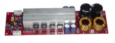
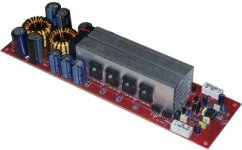
Finaly, I resolved noise. Signal audio cables from input jack to input conector on the PCB was bad, I changed and now everything is just fine. Even with 1n in input stage I dont have a noise, I have good mids and highs tones! Thank you everybady who help me with this!
On this picture is my new PCB, not to small 8.5 x 9cm but one side and it has protections. Model for TO247 and TO220 case of output transistrs (smaller then before).
For Signal and clip indicator I plan to use AN6884 (vu meter). Signal led is on second led and clip led is on the last. Input signal with 10K trim.pot I can adjust clip level. Is this good idea?
What do you think?
And one question more, what is better, 20uH with 1uF or 30uH with 1uF output filter on 250Khz res.freq. or higher freq. on example 300KHz?
Thanks
Attachments
Last edited:
Finaly, I resolved noise. Signal audio cables from input jack to input conector on the PCB was bad, I changed and now everything is just fine. Even with 1n in input stage I dont have a noise, I have good mids and highs tones! Thank you everybady who help me with this!
On this picture is my new PCB, not to small 8.5 x 9cm but one side and it has protections. Model for TO247 and TO220 case of output transistrs (smaller then before).
For Signal and clip indicator I plan to use AN6884 (vu meter). Signal led is on second led and clip led is on the last. Input signal with 10K trim.pot I can adjust clip level. Is this good idea?
What do you think?
And one question more, what is better, 20uH with 1uF or 30uH with 1uF output filter on 250Khz res.freq. or higher freq. on example 300KHz?
Thanks
Can you post full schematic and share PCB Gerber Files ?
What output Filter do you use ?
How can i buy a sample of them,i live in Europe.
How can i buy a sample of them,i live in Europe.DIGITCLASS CLASS-D POWER AMPLIFIERS MODULE T2400H.
T2400H SPECIFICATIONS:.
• 400W @ 8 ohms (+ /-90V).
• 750W @ 4 ohms (+ /-90V).
• 1400W @ 2 ohms (+ /-90V).
• 2200W@1.33 ohms (+ /-90V).
• 800W @ 8 ohms (+ /-125V).
• 1500W @ 4 ohms (+ /-125V).
• 2400W @ 2 ohms (+ /-125V).
• Input Impedance: 47k ohms unbalanced.
• Frequency Response: 20 Hz - 20 kHz.
• Supply Voltage: + /-45V to + /-125V.
• BIAS Voltage: 12V to 14V.
• Dimensions (W x H x D): 55 x 45 x 150 mm.
Price: 850.00 Baht
DIGITCLASS ™:.
DIGITCLASS CLASS-D POWER AMPLIFIERS MODULE HyperXD.
HyperXD SPECIFICATIONS:.
• 400W @ 8 ohms.
• 750W @ 4 ohms.
• 1400W @ 2 ohms.
• 2200W@1.33 ohms.
• Minimun load 1 ohm.
• Input Impedance: 100k ohms unbalanced.
• Frequency Response: 20 Hz - 20 kHz.
• Supply Voltage: + /-45V to + /-95V.
• BIAS Voltage: 12V to 14V.
• Dimensions (W x H x D): 55 x 50 x 200 mm.
Price: 1,290.00 Baht
woots:.
Released when offline is very interesting.
Old.
How can i buy some sample of these amp.The site is on thai language and i live in europe.DIGITCLASS CLASS-D POWER AMPLIFIERS MODULE T2400H.
T2400H SPECIFICATIONS:.
• 400W @ 8 ohms (+ /-90V).
• 750W @ 4 ohms (+ /-90V).
• 1400W @ 2 ohms (+ /-90V).
• 2200W@1.33 ohms (+ /-90V).
• 800W @ 8 ohms (+ /-125V).
• 1500W @ 4 ohms (+ /-125V).
• 2400W @ 2 ohms (+ /-125V).
• Input Impedance: 47k ohms unbalanced.
• Frequency Response: 20 Hz - 20 kHz.
• Supply Voltage: + /-45V to + /-125V.
• BIAS Voltage: 12V to 14V.
• Dimensions (W x H x D): 55 x 45 x 150 mm.
Price: 850.00 Baht
DIGITCLASS ™:.
DIGITCLASS CLASS-D POWER AMPLIFIERS MODULE HyperXD.
HyperXD SPECIFICATIONS:.
• 400W @ 8 ohms.
• 750W @ 4 ohms.
• 1400W @ 2 ohms.
• 2200W@1.33 ohms.
• Minimun load 1 ohm.
• Input Impedance: 100k ohms unbalanced.
• Frequency Response: 20 Hz - 20 kHz.
• Supply Voltage: + /-45V to + /-95V.
• BIAS Voltage: 12V to 14V.
• Dimensions (W x H x D): 55 x 50 x 200 mm.
Price: 1,290.00 Baht
woots:.
Released when offline is very interesting.
Old.
Thank for your time
@NMOS
I have paroblem with output coli because in my country I cant find Micrometals iron powder cores, feritte cores too. But I get by somehow.
This is pcb files, with components layout, artwork and schematic of whole board. On schmeatic you hava calculations for resistor in regard to Vcc pover supplay. TIP41c needs his own heatsink!!!
By the way, I still wait answer on my previous question about Vu meter like clip indicator and uotput coli inductance, if someone can answer on it.
Thanks
I have paroblem with output coli because in my country I cant find Micrometals iron powder cores, feritte cores too. But I get by somehow
.This is pcb files, with components layout, artwork and schematic of whole board. On schmeatic you hava calculations for resistor in regard to Vcc pover supplay. TIP41c needs his own heatsink!!!
By the way, I still wait answer on my previous question about Vu meter like clip indicator and uotput coli inductance, if someone can answer on it.
Thanks
Attachments
Last edited:
SPECIFICATIONS:
Supply Rang +/-75V to +/-100V
Sub Supply 9V-12V
Un-Balance Input
Input Impedance 100K
Low Noise
Class D Freq. Response : 20 Hz - 5000 Hz
Power Output 1600 watt@4 ohms
Power Output 2500 watt@2 ohms
Power Output 4000 watt@1 ohms SPECIFICATIONS:
Supply Rang +/-75V to +/-100V
Sub Supply 9V-12V
Un-Balance Input
Input Impedance 100K
Low Noise
Class D Freq. Response : 20 Hz - 5000 Hz
Power Output 2000 watt@4 ohms
Power Output 2800 watt@2 ohms
Power Output 5500 watt@1 ohms
Supply Rang +/-75V to +/-100V
Sub Supply 9V-12V
Un-Balance Input
Input Impedance 100K
Low Noise
Class D Freq. Response : 20 Hz - 5000 Hz
Power Output 1600 watt@4 ohms
Power Output 2500 watt@2 ohms
Power Output 4000 watt@1 ohms SPECIFICATIONS:
Supply Rang +/-75V to +/-100V
Sub Supply 9V-12V
Un-Balance Input
Input Impedance 100K
Low Noise
Class D Freq. Response : 20 Hz - 5000 Hz
Power Output 2000 watt@4 ohms
Power Output 2800 watt@2 ohms
Power Output 5500 watt@1 ohms
Attachments
...Thanks about the schematic but i need info about one Thai site that is selling DIGITCLASS amp kits..SPECIFICATIONS:
Supply Rang +/-75V to +/-100V
Sub Supply 9V-12V
Un-Balance Input
Input Impedance 100K
Low Noise
Class D Freq. Response : 20 Hz - 5000 Hz
Power Output 1600 watt@4 ohms
Power Output 2500 watt@2 ohms
Power Output 4000 watt@1 ohms SPECIFICATIONS:
Supply Rang +/-75V to +/-100V
Sub Supply 9V-12V
Un-Balance Input
Input Impedance 100K
Low Noise
Class D Freq. Response : 20 Hz - 5000 Hz
Power Output 2000 watt@4 ohms
Power Output 2800 watt@2 ohms
Power Output 5500 watt@1 ohms
- Home
- Amplifiers
- Class D
- UCD 25 watts to 1200 watts using 2 mosfets