The feature list. (What was more than half of your post.)
I can't see this means anything. And I ask you not to refer to me when writing things like this. Balanced and noninverting inputs behave very similarly. Unbuffered inverting input is totally different.
Oh good,
I was too fast responding

Not for inverting or not, by unbuffering then one input automatically grounded. Invert or not still have chance to get the same good sound. The IR2110 based from IR is use the same feedback like mine except pre and post, still have good sound.
I agree, it's not good. It's excellent.
Delay = not the dead time?
For me delay is dead time in reality. My big bulky PA amp dead time is not more than 50ms.
No difference. All principles are the same for any size. OK, above 2 kW other topologies and methods worth to be considered. I built some with 150V and 30A continuous output and 200 kHz switching freq about 8 years ago, and they were almost the same quality as the smaller ones. Instead of 0.1 % it has 0.3 % THD, but not 3 %! Others make 50 kW in one rack unit and much better quality. That is a big amp. We are nothing.
I mean if you start from very low THD from beginning from simulation, you will never get real amp but ash.
What a 50kW amp?
Sub amp I guest
Like yours as well
Last edited:
Sometimes people asking very simple circuit. By one input grounded, it cut many numbers of component so more more simple. So then, sometime you need to ask why someone create that amp, what the aim is.
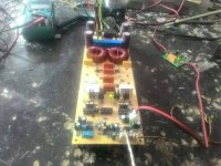
This is most simple UcD Discrete I have ever. PCB Made by Yadi, wong mbantul.
This is most simple UcD Discrete I have ever. PCB Made by Yadi, wong mbantul.
Attachments
Delay = not the dead time?
For me delay is dead time in reality. My big bulky PA amp dead time is not more than 50ms.
I'm not surprised you don't know what delay means. It is not dead time, but I can't teach you.
Oh good,
I was too fast responding
Not for inverting or not, by unbuffering then one input automatically grounded. Invert or not still have chance to get the same good sound. The IR2110 based from IR is use the same feedback like mine except pre and post, still have good sound.
I never said it was different in sound. I said different in input impedance and offset drift and source dependancy. Noninverting one is much better in this aspect and not significantly worse than the buffered inputs in any other aspects. I don't know what IR schematic you refer to, you'd better link it if you think it's relevant.
I mean if you start from very low THD from beginning from simulation, you will never get real amp but ash.
What a 50kW amp?
Sub amp I guest
Like yours as well
Sorry, "only" 40 kW:
PKN Controls
Yes, sub amp with 5Hz-60kHz bandwidth. And 0.05 % distortion at full power.
Mine worked from DC to ... I couldn't measure since my sound card didn't work over 20 kHz. But it followed square wave produced by sound card with less then 10 % peak error.
You don't have to be malitious.
Hi kees52,
Could you please upload .asc file from post http://www.diyaudio.com/forums/clas...00-watts-using-2-mosfets-431.html#post4938908 thank you!
Could you please upload .asc file from post http://www.diyaudio.com/forums/clas...00-watts-using-2-mosfets-431.html#post4938908 thank you!
Hey, theoretical smart guy of this topic. Stop bluffing! If your card doesnt give 20kHz , then the square wave cannot have harmonics above 20kHz [emoji12] .I couldn't measure since my sound card didn't work over 20 kHz. But it followed square wave produced by sound card .....
PS What a constructor are you ? If you dont have a simple signal generator?[emoji33]
I'm not surprised you don't know what delay means. It is not dead time, but I can't teach you.
Delay is for individual component i.e. delay on or off.
What a delay in an amp?
Are you creating sound effect or something?
Sorry, "only" 40 kW:
PKN Controls
Yes, sub amp with 5Hz-60kHz bandwidth. And 0.05 % distortion at full power.
Mine worked from DC to ... I couldn't measure since my sound card didn't work over 20 kHz. But it followed square wave produced by sound card with less then 10 % peak error.
You don't have to be malitious.
A sub up to 60kHz
I am confused
And very bad sound card which has limit your ability
Last edited:
I never said it was different in sound. I said different in input impedance and offset drift and source dependancy. Noninverting one is much better in this aspect and not significantly worse than the buffered inputs in any other aspects. I don't know what IR schematic you refer to, you'd better link it if you think it's relevant.
Do you Iraudamp1?
I dont know your problem
Invert or not is a choice. Pro con always there. But you cannit say that is wrong.
Anyway show your real working amp please
Not just always blaming other but no real working amp
Hey, theoretical smart guy of this topic. Stop bluffing! If your card doesnt give 20kHz , then the square wave cannot have harmonics above 20kHz [emoji12] .
PS What a constructor are you ? If you dont have a simple signal generator?[emoji33]
You right!
Unless he shows his real works his talks are meaningless
Full bridge 90Vdc supply prototype by our friend.
http://www.diyaudio.com/forums/class-d/301218-fullbridge-class-d-pa-ultra-high-power.html
http://www.diyaudio.com/forums/class-d/301218-fullbridge-class-d-pa-ultra-high-power.html
Attachments
I mean if you start from very low THD from beginning from simulation, you will never get real amp but ash.
What a 50kW amp?
Sub amp I guest
Like yours as well
50Kw 50000W Sub amp ?????????????????
you need >>>>>150dB SPL inside your room
this is Diyaudio not Dieaudio
for commercial music
just buy 10x 5000W amplifiers with audio consol system and speaker system with 100kw power generator
50Kw 50000W Sub amp ?????????????????
you need >>>>>150dB SPL inside your room
this is Diyaudio not Dieaudio
for commercial music
just buy 10x 5000W amplifiers with audio consol system and speaker system with 100kw power generator
Maybe not for human
I am still thinking how a 200kHz pwm class D can produce good full range amp.
Anyway, this is not a joke, a real thousand watts output DIY Class D amp.
Powered with Ex Cellular BTS Power Supply, Eltek Flatpack 2000, 4 pcs in series. To get 107Vdc at 37 ampere symmetric supply. Amplifier module is my design, D2KNeo with just one set IRFP4242. The amp can drive 4x18" speaker per channel easily. PWM speed is 300kHz.
https://www.youtube.com/watch?v=6lRclDT9IY0&t=24s
Last edited:
- Home
- Amplifiers
- Class D
- UCD 25 watts to 1200 watts using 2 mosfets