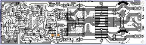
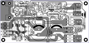
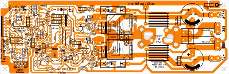
I have a question mister manoj, the power supply circuit this one you see (green) has DC protection or just a soft star circuit time delay seconds for the SPK out ? on lastly I made the updates from the AUD600 circuit you send me and it was difficult for me to find space for the components but I was able to do so, yesterday I forgot to add the 470nF 400V caps and now is on the PCB I think this will be a great project for me
Hi,
Yes its a DC protection with @3Sec delay(power On)
the ckt is deferent what i gave AUD600 Rev3.0.1
NB: nice PCB,pls check power cap(220uF/160v) is wrong direction.
Regards
MANOJ
Hi,
Yes its a DC protection with @3Sec delay(power On)
the ckt is deferent what i gave AUD600 Rev3.0.1
NB: nice PCB,pls check power cap(220uF/160v) is wrong direction.
Regards
MANOJ
oh my God yes you right sir, how did I not notice that ?
 I apologize I will corrected
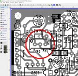
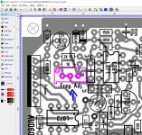
one question sir, I do not own an oscilloscope to adjust frequencies what value resistor for normal operation "stable and good" and also another question, will this work with 55V +/- rails ? I'm guessing value of this resistors that are selected on the image they need to be change right ?
oh yeah I do like this layout that is why I decide to tweaked a bit
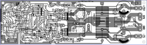
also I a made the re-drawing of the power supply I know that the schematic is different but if this first version is good to go I can used let me know when you get a chance sir is the version supply is ok to use good day sirBest Regards
Juan
Attachments
Looks like it's clocked FB amp and not an UCD. Could please share the schematic?Hello
greetings time to try full bridged d class
warm regards
Andrew
500R-1k - adjust frequencies
is from 500R to 1K adjustment right ? this is the last image of the layout I made some changes I will continue checking later for bugs from me self
I don't even trust myself lolAttachments
Last edited:
adjustment of the frequency depends on the ratings of the capacitor and resistor feedback. What denomination are you, I do not know. Therefore, I can not say exactly. The higher the value of the trimming resistor, the lower frequency
I'm thinking to run the amp only to 8 ohms load and lower rail voltages example 55V +/- ,I'm not interested in push the amp too much only to have it working correctly and nicely stable for decaf music that I like
if 55V rails can not be use I do not mind get me a 55 -0- 55 toroid I will continue reading here the different post the info most be somewhere else here sir
Best Regards
Juan
Directly opposite .The higher the value of the trimming resistor, the lower frequency

Last edited:
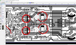
hello guys if some one can help me I will appreciated , I notice that they are 2 MUR1560 place on the drain cathode to source anode I need to know if I can use 1N5408 instead what I did I just leave both options on the PCB just in case, and last question what is the purpose of those two diodes ?
Regards
Juan
, I notice that they are 2 MUR1560 place on the drain cathode to source anode I need to know if I can use 1N5408 instead what I did I just leave both options on the PCB just in case, and last question what is the purpose of those two diodes ?Regards
Juan
Attachments
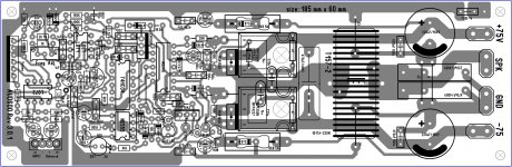
hello gentlemen can some one give a revision of this PCB's  I'm worried that it might have errors from me if any help I be happy to share PDF file after all is correct, I do not mind share guys
  yes indeed, also I'm thinking to order a few PCB of the AUD600 Rev 3.0.1 and supply too but need your help guys I will appreciated any help
Best Regards
Juan
I'm worried that it might have errors from me if any help I be happy to share PDF file after all is correct, I do not mind share guys yes indeed, also I'm thinking to order a few PCB of the AUD600 Rev 3.0.1 and supply too but need your help guys I will appreciated any help Best Regards
Juan
Attachments
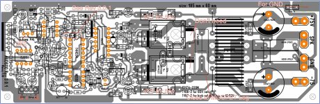
Hi,
see text and correct
Regards
MANOJ
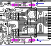
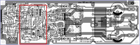
hello sir thank for your help, so the filter cap 470nF/400V need to be as closer the mosfet legs ? yes I can do that, I fix trim pot value to 2K2 and input polarity corrected, and took out the two 1N5408 out of the board, the only thing that got me confuse is the 1N4148 diode I look at the schematic Rev 3.0.1 and I notice that pin 3 U1 has been connected to that diode to the anode then the cathode is connected to a 470nF and the other leg is connected to red LED cathode ..... uhmmmm?
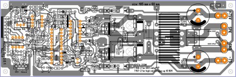
 I think I have to figure out how to updated that sir, well I'm gonna see if I can fix that and I will post image after I'm done sir this is the last image and I think I have to move to coil so the board is not that big or better say longer, the red rectangle is where I have to work with or better say brainstorming lol
 ok sir good day thanks
I will post later Best Regards
Juan
Attachments
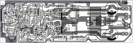
Mister manoj I made some more changes to the AUD600 Rev 3.0.1 please when you get a chance or better say time check layout, the new thing I did is add at least more than 3 options coil with part number 1D17A-220M 22uH 6A, VER2923-333KL 22uH coil craft 100A or the regular rings T157-2 or T106-2 actually 4 options
Regards
Juanhttp://www.diyaudio.com//www.pinterest.com/pin/create/extension/
Regards
Juanhttp://www.diyaudio.com//www.pinterest.com/pin/create/extension/
Attachments
- Home
- Amplifiers
- Class D
- UCD 25 watts to 1200 watts using 2 mosfets