do make sure that all the mosfets are still working and none have burned. if there's a short in any of the mosfet pin then it's probably toasted.Ok thanks have change diode 1N4148 look pics
then have check my board all look ok
Then After connect with Rail Ics and Mosfets are cold
Green Led flash short time and speaker make plopp after connect with rail.
Amplifier have no DC at outpurt all looks ok,
After disconnect Rail green Led flashs about 3 seconds and speaker make plopp plopp plopp plopp
But Im worry now,... no music comes out.
have replace all ICs but same like before, no music comes out
Then have amp connect with PC Soundcard, with maximum Volume output from Soundcard I get distortion noise
I dont know what can I do to get music?
I cant see fault in Board, any idea to solve problem, have upload pics from Board
if i were you i'd remove the extra mosfet and make the circuit stable with a single pair first before adding more.
Mosfet ok have only 1 pair Voltage ok, TL071 have 5 V DC
have replace today 25401 and CD4049 but always same no music.
After connect rail... greend led flash very short and speaker make short time noise and I see shot time low Voltage at speaker output then voltage is about 0 V DC
after 30 seconds amp starting make noise like bab - then 4 sec. braek - bab then again all time
Im feeling like oscolllator not working,
I dont know what can do, dont find short traces and devices cold
Can I check with Voltmeter where the amp fail ? any idea
Hello again,...
no music cant find connected traces and dont know what is wrong
Have check Voltage to GND , who can compare with working IRS4K5 or similar Model ?
all ICs and Mosfets are not warm
TL071 IC
Rail Voltage +/- 5,6V
PIN 6 output show 4,80 V before 1 K resistor to 2n5401
is 4,80V at output ok ?
IR2110
VCC - VDD - HIN show 68,2 V
LO - COM - SD – LIN – VSS show 80 V
Vs have peaks between 0 – 100 mv (changing all time)
VB have peaks between 0,5 and 3 Volt (changing all time)
Ho have have peaks between 0 and 0,5 Volt (changing all time)
Rail is +/- 80V DC
Bias Voltage 12 V DC external Supply
Last edited:
this is where it gets really hard building a class D, finding fault when you don't have access to a scope.
it would be much much easier to trace the culprit if you connect it to a scope as you can't possibly check the signals just by using a multimeter.
if you have a scope check the signal output after tl071. if that's working fine check the signal output after transistor. then check the signal into the inverter. then check the signal from the inverter to the ir2110 driver. you'll pinpoint the culprit in no time.
the voltage output does swing rapidly, as it's outputting triangle and square wave.
either trace it with a scope or it's a shot in the dark. even the small paper caps close to the tl071 to generate the triangle wave have a big impact. not all type works.
by the way lower your voltage rail during troubleshooting. better still, limit the current that's going to the amp. remove any high capacity power reservoir caps and discharge any rail caps. the amp should still work with around 20-30V rail. a good working class d should only use <0.5A during operation.
limit the voltage and current and limit your risk. 80V is much too dangerous to be working with your bare hands.
Hello!
I lost some time and among many messages ... What happened to the onset UCD design theme?
Still working with the design and it has never failed one. I see that there have been other diagrams and do not work quite right.
It is something to adjust here and there ... The design is good and can be very reliable and respectable power.
Greetings!
D
Deleted member 148505
Have make IRS4K5 but big Problem, not working !
NE555 and LM311 very hot after 1 minte
You can check the protect circuit by only powering up the bias supply.
Set your multimeter to diode test mode.
Insert the positive probe of the multimeter to pin 3 of lm311, and negative probe to the current sense resistor connected to -B track.
That should form voltage that can be sensed by your protect circuit.
If the red LED didn't light up, there's a problem with your circuit.
D
Deleted member 148505
any substitute UF4004? Instead MUR series thanks
according to DT4-04
The diode must have a BV > DC+ and a fast recovery time
(trr < 100 ns) to minimize the amount of charge fed back from
the bootstrap capacitor to V
CC
supply.
Hello!
I lost some time and among many messages ... What happened to the onset UCD design theme?
Still working with the design and it has never failed one. I see that there have been other diagrams and do not work quite right.
It is something to adjust here and there ... The design is good and can be very reliable and respectable power.
Greetings!
it is a good amp design but it is tricky to drive it with high voltage such as +/-70 to +/-95vlts
")
aud 900 with protect in one board on the way
Hi stewin,
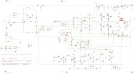
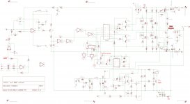
found mistake in your schematic
Regards
MANOJ
Last edited:
Hi stewin,
found mistake in your schematic
Regards
MANOJ
hi sir manoj please do tell me so i can rectify
D
Deleted member 148505
Hello!
I lost some time and among many messages ... What happened to the onset UCD design theme?
Still working with the design and it has never failed one. I see that there have been other diagrams and do not work quite right.
It is something to adjust here and there ... The design is good and can be very reliable and respectable power.
Greetings!
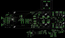
Hi,
Just out of curiosity...would like to know which is this software you are using for making schematics and boards???
Regards,
thanks manoj you are a true diy angel.
thanks jlester . it is said in the forums the more voltage you use, the value of c11 has to be decreased for example irs4k5 . but i am very open to change the value if it is suppose to be changed.
thank you all i will post correction later in the day.
You can increase the size of your C11 to 100uf since you didn't provide a bootstrap resistor in the schematic.
thanks jlester . it is said in the forums the more voltage you use, the value of c11 has to be decreased for example irs4k5 . but i am very open to change the value if it is suppose to be changed.
thank you all i will post correction later in the day.
D
Deleted member 148505
thanks manoj you are a true diy angel.
thanks jlester . it is said in the forums the more voltage you use, the value of c11 has to be decreased for example irs4k5 . but i am very open to change the value if it is suppose to be changed.
thank you all i will post correction later in the day.
No, the value of the bootstrap capacitor is computed by the RC time constant formed with the bootstrap resistor.
Since you don't have the bootstrap resistor in the schematic. The charging of the bootstrap cap will not be delayed. So you can use a higher value for that.
The amplifier's oscillation will not start if the RC time constant is too high. Around 55us is good.
For more info read DT99-7
thanks jlester. i wil replace with 100uf
- Home
- Amplifiers
- Class D
- UCD 25 watts to 1200 watts using 2 mosfets