Delta sigma however requires high order modulators in order to push noise out of the audio band which calls for complex circuits of several comparators and integrators in series, so for simplicitys sake i prefer UcD over delta sigma.
Basically post filter feedback from what i've seen over the years on this forum is the way to go for self oscillating class d amplifiers, wheres clocked designs is a waste of time.
Basically post filter feedback from what i've seen over the years on this forum is the way to go for self oscillating class d amplifiers, wheres clocked designs is a waste of time.
From what i read, post filter feedback has advantages above pre filter feedback such as beeing load invariable, ie the switching frequency is defined, not 200kHz for a 2 ohm load and 600kHz with a 8 ohm load and 400kHz with a 4 ohm load and such like pre filter feedback topologies. As well as beeing flat over the 20-20000Hz audio band instead of only beeing flat at the designed load impedance wheres on 8 ohms freq response peaks at higher frequencies and ohm 2 ohm load freq response starts drooping at a lower frequency than on 4 ohms.
Atleast this is what i read, assuming its not just marketing bullsh*t by Hypex to boast their UcD sales.
Maybe Bruno himself has some input on this ?
Atleast this is what i read, assuming its not just marketing bullsh*t by Hypex to boast their UcD sales.
Maybe Bruno himself has some input on this ?
My all amplifiers
My all amplifiers tested successfully on full night of 14 april
DSCN4212 - YouTube
warm regards
Sameerx1
My all amplifiers tested successfully on full night of 14 april
DSCN4212 - YouTube
warm regards
Sameerx1
Attachments

My all amplifiers tested successfully on full night of 14 april
DSCN4212 - YouTube
warm regards
Sameerx1
 Thank you.
Definitely one of the preferable types for classD.
Besides low gate charge and low RDSon it has a good body diode with low Qrr and also IR specifies a high dv/dt rating.
From my conservative view it is fine for rails up to +/-65V.
Considering +/-65V and switching frequencies around 400kHz it can easily feed 4R loads from a half bridge and still has good headroom for impedance dips of the load.

current rating its depend what type of mosfet you are using, 20-30 amp is enough. Btw you can give a try and tell us the result.
been a while since i last stopped by.I cannot try the IRFB4615 as i don't have any...yet.
anyway while i don't have any IRFB4615, i've been using IRFB5615 for quite a while now.
IRFB4615 150V 35A 0.039 26NC
gate charge Qg (nC)(typical/max) 26/26
trr (ns)(typical/max) 70/83
qrr (nC)(typical/max) 177/247
IRFB5615 150V 35A 0.039 26nc
gate charge Qg (nC)(typical/max) 26/40
trr (ns)(typical/max) 80/120
qrr (nC)(typical/max) 312/468
as you can see, the rated specs are quite similar, but the 5615 are sold at nearly ~50% less compared to the 4615 here. so i'm using them since they're cheaper.
i've tested running them at 800khz and they're stable at that frequency. currently they're running at ~200khz, 50V rail to 2 ohm load. got good result drawing ~1kw out of them.
previously i've even mistakenly wired them to a short and it took them around a good 10-15 second before blowing up. they're more robust compared to lower voltage mosfet that i've used before.
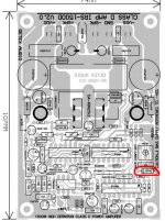
AUD600 PCB IRFP4768 Mosfet and AUD600 PCB with 2 Mosfets totem pole driver
Hello Guys
Nobody want give or share PCB files for supplier, often same with schematic, people make big secret
Detex Audio Thailand dont sell IRS amplifier Boards to me and friends,
he say, dont sell for foreigner and Thai People have foreigner friends,
crazy this guy !
I get angry this week and design AUD600 PCB by myself !
I accept to share files for PCB supplier and schematics with other DIY
Only manojtm share AUD600 schematic with me....
Have design double Layer PCB for AUD600
- add DC protect Crowbar (thanks to APEX)
- add Led for Power - Signal and Clip (thanks to APEX)
Attachments:
AUD600 PCB IRFP4768 Mosfet with Crowbar and LED Power - Signal - CLIP
AUD600 PCB with 2 x IRFP4768 Mosfets with totem pole driver, Crowbar DC protect and LED Power - Signal - CLIP
Attachments
Hi Insomnia,
Thank you for using AUD600 amp
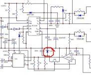
I am not discouraging you, your PCB design is not good for class D big GND loop will create more EMI in to the input and it will create cross talk when you using 2nd CH. Using Ground plane for reducing EMI
2. Use c18 close to the MOSFET for reducing EMI & RF
3. I am not suggesting crowbar for class D b'cause any issues causes in your PCB/components will create -Ve supply comes in SP line and it will damage 7414,2110 and MOSFET.
Regards
MANOJ
Thank you for using AUD600 amp
I am not discouraging you, your PCB design is not good for class D big GND loop will create more EMI in to the input and it will create cross talk when you using 2nd CH. Using Ground plane for reducing EMI
2. Use c18 close to the MOSFET for reducing EMI & RF
3. I am not suggesting crowbar for class D b'cause any issues causes in your PCB/components will create -Ve supply comes in SP line and it will damage 7414,2110 and MOSFET.
Regards
MANOJ
Hi Insomnia,
Thank you for using AUD600 amp
I am not discouraging you, your PCB design is not good for class D big GND loop will create more EMI in to the input and it will create cross talk when you using 2nd CH. Using Ground plane for reducing EMI
2. Use c18 close to the MOSFET for reducing EMI & RF
3. I am not suggesting crowbar for class D b'cause any issues causes in your PCB/components will create -Ve supply comes in SP line and it will damage 7414,2110 and MOSFET.
Regards
MANOJ
Hi Manoj:
How about my one? http://www.diyaudio.com/forums/class-d/226812-my-class-d-amp-27.html#post3456368
Please suggest me changes, I will start making code if pcb is okay. Let me know if you need DC protect schematic.
Thanks
Raj
SUCKS! No ground plane, long current loops asking for EMI galore, no good.
Thanks a lot for your feedback. Now please help me where to change and what?
This is single layer pcb, how to give gnd pane? How long current loops is allowable?
Thanks again.
Raj
- Home
- Amplifiers
- Class D
- UCD 25 watts to 1200 watts using 2 mosfets