hi whortless
which is the best transistor to use as buffer in totem pole . to drive 4 pairs irfb 4227 or irfp250 or irfp264 or (irf640 6pairs)?? will the 2SB772/2SD882 work or there is a better pair.
Hi,
I never used totem pole drivers after a specially designed IC. Never need to use one except the previous discrete UCD amps. However, They should be high HFE and low Vce sat. ones. They should be for switching purpose. The Vce of the complementary pairs are not so important if they can work within the Vboost or Vdrive voltage range. Hence, the pairs i suggested can do the job. In my previous designs i used philips 5240T as fast turn off. And used Maxim 7.2A SOT23 mosfet driver to drive heavy mosfets like IRFP250.
In my view BD911/912 can be used as an output of a 50-70W class AB amp and using them as totem pole drivers not a logical approach to Class-D design. There are several BJTs around from Sanken, ZETEX or Philips for this purpose. Try to find out best for your purpose. Try to get a set of transistors as samples.
Good luck,
BW
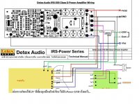
Dont forget the lower conextion the gnd from v rails to the gnd input (single wire)
have u built it? there's even some difference between the schematic and the pcb. but the most problematic is the cd4049 pinout which is totally different from the datasheet and schematic compared to the pcb. the pcb shouldn't work, but i wonder if anyone did manage to.
I use BD244/BD243 with 4 irfb4227.
they are same as tip41 and tip42?
Last edited:
 hi guys please help this amp works fine with +/-45vlts 8amps with irf540/540n/640n two pairs . they dont even warm when playing loud without a heat sink.
 but when using irfp250 /irfb4227 two pairs at +/-60vlts 1amp they get hot in the few seconds of playing. pls help me out guys

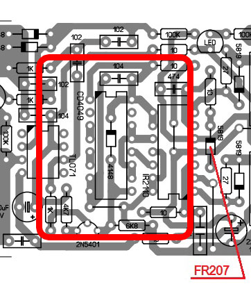
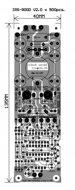
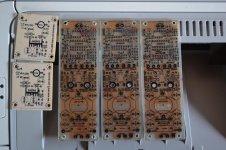
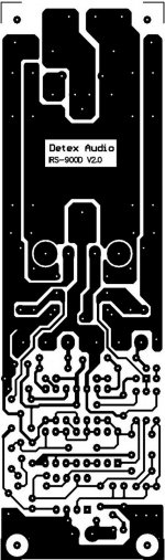
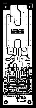
artwork and pcb diysmps
thanks in advance
Attachments
Last edited:
thanks Whortless i,ll try bc327 and bc337 do they meet the requirements?
It depends on what speed and current (Cg) you will work. BC639/640 seems better.
have u built it? there's even some difference between the schematic and the pcb. but the most problematic is the cd4049 pinout which is totally different from the datasheet and schematic compared to the pcb. the pcb shouldn't work, but i wonder if anyone did manage to.
can you post some photo so we can see what, where is the problem
top and bottom
i managed to make this thing work but dint get any much success......on low volume it works as clean as a headphone does but when increase volume there is a distortion in the speakers...like someone is tearing papers......help me out with this issue??????
I think your output filter not good or not matched (saturated) with current freq.. pls provide your schematic
RGDS
MANOJ
haven't built the pcb yet. i was contemplating to either redraw the schematic and include the 12v aux supply and a dc protection or just etch the pcb provided by thienchay at post #2101 & #2102.can you post some photo so we can see what, where is the problem
top and bottom
seeing how simple it is i redraw the schematics when i see the pinout of the cd4049 is different compared to the pinout used in cheshta's and thienchay's pcb. so i was wondering if anyone have etched and built the irs900 using cheshta or thienchay's pcb.
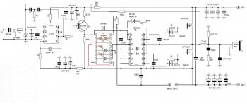
here's the original schematic of the irs-900d posted by cheshta:
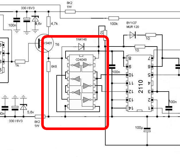
together with the cd4049 pinout from his post:
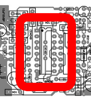
a remake of the pcb from thienchay:
and he's the pinout from cd4049 datasheet:
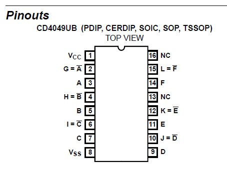
pin 7 and 8 shouldn't be shorted together and some other error. or am i reading it wrong somewhere?
would really love to hear any feedback from people who have built the irs900.
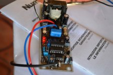
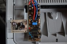
i don't have schematic i only made the amp without it and its working great
i only use detex file to make the pcb
i only use detex file to make the pcb
Attachments
Last edited:
I apologize because i'm did not checking carefully schematic of Detex .
I think they deliberately show the wrong schematic , but given right PCB .
And i recheck it , they just used 2 NOT gate of CD4049 on their PCB , and it is right , orther NOT Gate is not used .
This is the schematic i redraw .
I think they deliberately show the wrong schematic
, but given right PCB .And i recheck it , they just used 2 NOT gate of CD4049 on their PCB , and it is right , orther NOT Gate is not used
.This is the schematic i redraw .
Attachments
i don't have schematic i only made the amp without it and its working great
i only use detex file to make the pcb
thanks guys!I apologize because i'm did not checking carefully schematic of Detex .
I think they deliberately show the wrong schematic
And i recheck it , they just used 2 NOT gate of CD4049 on their PCB , and it is right , orther NOT Gate is not used
This is the schematic i redraw .
that's all that i needed to hear. the schematic is indeed with error. now that i have you guys that have built a working pcb i know not to follow the schematic and build the amp according to the posted pcb.
thanks again guys
i don't have schematic i only made the amp without it and its working great
i only use detex file to make the pcb
its not only working great its powerful also!
its not only working great its powerful also!
what voltage did you use and was the outputs heating ?
- Home
- Amplifiers
- Class D
- UCD 25 watts to 1200 watts using 2 mosfets