Florin,
If you want pulse by pulse current limiting, it is best to use a current mode controller, as you have decided.
However, there is a problem with your circuit. The current sense transformer will not work properly, because the average current through the primary will not be zero. You could do a couple of things about this. The easiest is to replace the transformer with a sense resistor. Another would be to use two primaries, one in eash FET source, connected such that the currents (fluxes) are opposite. Finally, you could put the transformer in series with the power transformer. You should also remove the diode from the current sense network. A large coupling cap in series with the power transformer will also help to eliminate flux imbalance.
You should add some resistors is series with the FET gates.
Rick
Rick,
Thank you for your comments.
- Sense resistor - a sense resistor is still an option since I have not decided yet if the PWM controller will be on the secondary side.
The full bridge is going to have a PFC in front and supply will be fed through an usual 50Hz transformer (pcb mounted). So, if the PWM controller will be placed on primary side, then I can use the same supply source. Of course, the feedback circuit will be optocoupler based.
- Two primaries for current sense transformer - I can also do it
- Large coupling capacitor - this is what I was trying to avoid
- Remove diode from current sense network - I think it is current sense transformer design dependent ...
- resistors in series with FET gates - the "gate drive circuitry" includes gate resistors
Florin
 .
.Dexter,
The series capacitors are subject of current ripple. One or maybe two high quality capacitors are required. I don't have enough trust in those cheap Chinese (no offense) parts that can be found in pc smps.
I think that few logic gates is not such a big complication when you know how to properly close the current loop. Moreover, peak current mode control offers some advantages over voltage mode control that I would like to have.
A bigger core will not be practical and I think will not avoid the saturation problem.
Actually, you should use two separate current sense transformers with rectified outputs (in a way that lets them reset, load resistor after diode). Otherwise the same DC current imbalance that saturates the main transformer will also saturate the current sense transformer and then it will blow up!
It might not even work at all, as the control circuit needs to be able to sense the DC current through the transformer which it can't do with one current sense transformer.
It might not even work at all, as the control circuit needs to be able to sense the DC current through the transformer which it can't do with one current sense transformer.
megajoke
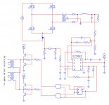
The dc/dc converter has a pfc in front of it. I moved the pwm controller to the primary side and I synchronized both controllers
I used a sense resistor and a differential opamp like in the TI app note (see link)
http://focus.tij.co.jp/jp/lit/an/sloa044/sloa044.pdf
The pulse by pulse current limiting should avoid transformer saturation.
The supply voltage of differential amplifier is the same as for pfc controller (low power 50 Hz pcb mounted transformer + linear reg).
Voltage feedback circuit includes an optocoupler and a TL431.
Only the pfc was built and I'm still waiting for a variac (stelltrafo) to do the proper tests.
The dc/dc part is only a schematic (no layout yet) due to my limited time...
The hole system must deliver +/-75V @1kW. Finally it should power an audio amp.
Sorry for my late response....
The dc/dc part is only a schematic (no layout yet) due to my limited time...
The hole system must deliver +/-75V @1kW. Finally it should power an audio amp.
Sorry for my late response....
greatdane,
unfortunately there's no progress with this project. I was working on other things (a classD amp) and simply I didn't have enough time to take care of it.
I appreciate your intention to support. I will contact you when the project will be "resuscitate" (most probably next year).
Regards,
Florin
unfortunately there's no progress with this project. I was working on other things (a classD amp) and simply I didn't have enough time to take care of it.
I appreciate your intention to support. I will contact you when the project will be "resuscitate" (most probably next year).
Regards,
Florin
- Status
- This old topic is closed. If you want to reopen this topic, contact a moderator using the "Report Post" button.
- Home
- Amplifiers
- Power Supplies
- UC3846 current mode control vs. SG3525 with average current mode control