if you're planning on spending much time in DIY realm, the investment in a cheap router and a few bits will more than pay for themselves.
don't be surprised if things take longer than you planned.
best of luck, and keep us posted
chris
I bought a mastercraft router with a bunch of router bits included, and a Jasper jig for cutting holes. Don't know how to use it for 45 deg. chamfers.
And yes, this will take some time to do. Have to work out the bracing for the rear door, and cabing with the movable shelves.
Any suggestions for the rear door and 45 deg. chamfers would be great. Do you know of a good DIY woodworking website?
Will be away on a buisness trip for a month, so I'm trying to get as much done this week.
Thanks again for your help.
I bought a mastercraft router with a bunch of router bits included, and a Jasper jig for cutting holes. Don't know how to use it for 45 deg. chamfers.
couldn't be simpler:
Chamfer Bits
An externally hosted image should be here but it was not working when we last tested it.
These can be used hand held for circles or full perimeter edges, or set up in shop made router table with guide fence for single edges only. In other words, the only bit you use in the Jasper jig is a 1/4" plunge bit, for which it is calibrated. I personally prefer something like an up-cutting spiral bit - if you're planning on more than a couple of pairs of speakers, the quality bits pay huge dividends.
An externally hosted image should be here but it was not working when we last tested it.
Note that without an extension block, it's too easy to wrap further around an outside corner than you planned. For chamfering the rear side of driver cutouts, you'll need to leave at least a 1/4" depth from the front side for the bearing. This is fine because on most of the smaller drivers, there isn't a lot of margin between the driver cut out and mounting screw holes. Too deep a chamfer and /or flush mounting rebate on the front of the baffle, and you'll not have much core for the hardware.
(there's where you use the MDF - for testing your setup and building the table and jigs/extension blocks. )
IINM, Mastercraft is a Cdn Tire house brand - they might well carry similar bits with their own name. Do not waste money on High Speed Steel bits without bearings for any edge treatment - profile, flush trimming or pattern following.
If you've run out of plywood for bracing, you could use rips of solid lumber such as birch, maple, oak, or even Doug fir. In corners they can be as small as 1x1, and if crossed and interlocked between perpendicular panels, they needn't be any larger dimension than 1x3 (nominal).And yes, this will take some time to do. Have to work out the bracing for the rear door, and cabling with the movable shelves.
Any suggestions for the rear door and 45 deg. chamfers would be great. Do you know of a good DIY woodworking website?
Will be away on a buisness trip for a month, so I'm trying to get as much done this week.
Thanks again for your help.
Last edited:
Latest Build
Thanks chris and dave.
Here's the latest update:
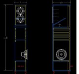
- Sub woofer baffle is doubled to 1" total
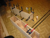
- Construction is underway, top half is about done.
- I had a 45 chamfer bit in my kit, didn't realize that the bottom was a bearing, I thought this could only be used on a straight edge. duh.. Works great.
- Used T-nuts for the FE167E
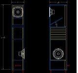
Drawing shows about five shelves spaces. Volume starts at about 13L to about 22L
Thanks chris and dave.
Here's the latest update:
- Sub woofer baffle is doubled to 1" total
- Construction is underway, top half is about done.
- I had a 45 chamfer bit in my kit, didn't realize that the bottom was a bearing, I thought this could only be used on a straight edge. duh.. Works great.
- Used T-nuts for the FE167E
Drawing shows about five shelves spaces. Volume starts at about 13L to about 22L
Attachments
Initial Sound:
First time round, the cabinet was overstuffed and it sounded choked. I put a 2" thick packing foam(which is somewhat dense) at the terminus, and used polyfil throughout. I got it balanced good now.
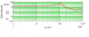
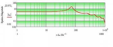
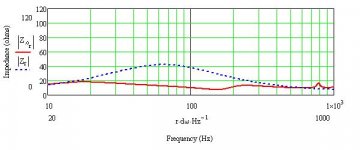
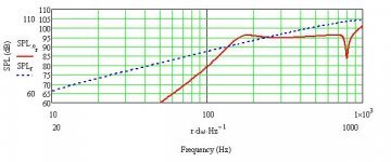
The drivers have been broken in pretty good now from my previous TQWT. So, initial thoughts are Wow, the transients and attacks have returned. Percussion and drums sound more realistic to me now. String plucking and bass slaps are more present. It's like I could hear the bow of a violin hit the first string, or that initial burst of air from Miles. It seems that the driver is not required to move as much air as it did before in this smaller taper, which also makes sound a bit more relaxed and even. The terminus velocity is a lot higher than my original TQWT. See plots.
I don't have the BSC connected, not sure if im gonna need it with the SDX7.
The LF is not as low as my original TQWT, but the attacks are there. Kick drums fundamental are at around 100Hz, and the velocity at the terminus is around 100Hz as well, which may explain this too.
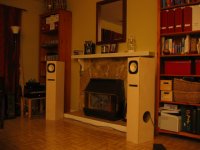
I'm enjoying the sound of these, can't wait to hear them with the SDX7's in the room. Need to finish my XO now.
First time round, the cabinet was overstuffed and it sounded choked. I put a 2" thick packing foam(which is somewhat dense) at the terminus, and used polyfil throughout. I got it balanced good now.
The drivers have been broken in pretty good now from my previous TQWT. So, initial thoughts are Wow, the transients and attacks have returned. Percussion and drums sound more realistic to me now. String plucking and bass slaps are more present. It's like I could hear the bow of a violin hit the first string, or that initial burst of air from Miles. It seems that the driver is not required to move as much air as it did before in this smaller taper, which also makes sound a bit more relaxed and even. The terminus velocity is a lot higher than my original TQWT. See plots.
I don't have the BSC connected, not sure if im gonna need it with the SDX7.
The LF is not as low as my original TQWT, but the attacks are there. Kick drums fundamental are at around 100Hz, and the velocity at the terminus is around 100Hz as well, which may explain this too.
I'm enjoying the sound of these, can't wait to hear them with the SDX7's in the room. Need to finish my XO now.
Attachments
A mechanics stethescope is a very useful tool for figuring out where the box is insufficient.
dave
I think i learned something about stuffing today. I put my ear on the cabinet and listened to the sound of the music, when I moved my ear around the cabinet, I could hear really bad ringing in places. At that point I would add a bit more stuffing. They were usually around the corners. I think a stethoscope could be more useful for this.
One thing bothers me, you combine a high sensitivity speaker like FE167E with a low sensitivity woofer...9db difference...how will this be compensated? by reducing the sensitivity of the high sensitive driver I presume...
This is intended for a bi-amped system with separate volume control for each speaker. Effective volume, balance and EQ with 4 dials. So efficiency does'nt really matter here too much. Just turn up the bass and/or turn down the midrange hi's.
I won't mess with the FE167E. I think it will be happy getting current from a NP Firstwatt F3. See http://www.firstwatt.com/downloads/cs-amps-speakers.pdf for power transconductance amps with full range drivers. A BSC circuit might not be needed either. A future update will be getting my FE167E eNaBled.
I built a DIY gainclone based on the LM3886 Chip which I will use for the SDX7. Gainclones have a somewhat high damping factor which should be good.
I'm currently working on a buffered PLLXO. Something similar to the NP B4.
See sketch in this thread http://www.diyaudio.com/forums/soli...d-active-crossovers-open-baffle-speakers.html
Not sure if his design will be published publicly, but it is the perfect device for biamping with full range drivers. It's not yet for sale either.
I made a DIY B1 buffer, and it's sitting in front of the gainclone powering the FE167E's and it makes a HUGE difference in the sound when you have proper impedance matching, so a B4 type circuit is the way to go for me. Perhaps one running dual supply that is regulated to get rid of the bypass caps in the signal path.
The biggest risk of this design is placement of the speakers FE167E and SDX7 within this cabinet, I tried to physically spread out with the driver, port and sub. But it's really unknown to me how it will sound in the room. From simple listening tests with the current speaker build and just firing up the SDX7 from another amp with no crossovers it sounded very promising.
The hard part now is getting a buffered XO system to work with both the FR and Sub in this cabinet. Adjustable electronic XO and adjustable Q point with removable shelves gives me a bit of a tweak factor and many hours of listening this system to get it right. I estimate that it will take several months.
Another Variation
After hearing these EL70's at CSS. I almost thought about replacing the FE167E with Dual EL70's wired series like Bob's at CSS.
Possible future addition is to have these interchangeable with the FE167E's in the same cabinet. (Sometime next year perhaps, wife permitting, yes I have a budget.") )
)
One of the differences is that the stuffing will have to probably change dramatically for each speaker swap. There is a bit of ringing.
Need to think about a supra baffle/speaker caddie for each FR system. What are the choices of materials. Hardwood, softwood, MDF, non-wood?
I guess something more ridgid?
After hearing these EL70's at CSS. I almost thought about replacing the FE167E with Dual EL70's wired series like Bob's at CSS.
Possible future addition is to have these interchangeable with the FE167E's in the same cabinet. (Sometime next year perhaps, wife permitting, yes I have a budget.
)One of the differences is that the stuffing will have to probably change dramatically for each speaker swap. There is a bit of ringing.
Need to think about a supra baffle/speaker caddie for each FR system. What are the choices of materials. Hardwood, softwood, MDF, non-wood?
I guess something more ridgid?
Attachments
Need to think about a supra baffle/speaker caddie for each FR system. What are the choices of materials. Hardwood, softwood, MDF, non-wood?
I guess something more ridgid?
yup, them EL70's are quite interesting little driver
if you're planning on swapping baffles, I think the choice of method to attach to main enclosure could ultimately be as important as the material for the baffles themselves.
I'd be inclined towards either hardwood cleats screwed to the perimeter of the baffle opening and threaded insert fittings, or 3/4" x 3/4" x1/4" aluminum angle, tapped for machine screws.
For the baffles, as they'd not be permanently glued to the enclosures, but rather sealed with weatherstripping, etc., you'd be free to play with solid woods, plywood, 1/4" or thicker aluminum plate - the sky's the limit. I've always wanted to find an excuse to try aluminum plate.
Thanks Chris.
I'd like to try different hardwoods. Give's my a chance to play around with the router a bit more.
I used T-Nuts to attach the FE167E, don't know If I can re-use those in the same location. We'll see.
Bpllxo
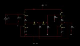
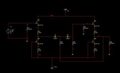
Circuit Description:
- Dual supply with JFET source followers
- Sallen Key circuit
- Linkwitz Riley 2nd order
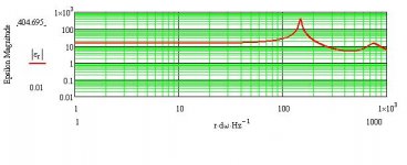
The simulation comes out okay, the frequency range for the XO should suffice the output Impedance of this circuit. Calculated range is about 40Hz to 400Hz, without too much loading issue. If so, a "white follower" can be employed.
References:
http://www.borbelyaudio.com/adobe/ae699bor.pdf
Crossovers
ESP - The Linkwitz Transform Circuit
http://en.wikipedia.org/wiki/Sallen–Key_topology
The Art of Electronics, 2nd Edition, Horowitz and Hill, 1989
Circuit Description:
- Dual supply with JFET source followers
- Sallen Key circuit
- Linkwitz Riley 2nd order
The simulation comes out okay, the frequency range for the XO should suffice the output Impedance of this circuit. Calculated range is about 40Hz to 400Hz, without too much loading issue. If so, a "white follower" can be employed.
References:
http://www.borbelyaudio.com/adobe/ae699bor.pdf
Crossovers
ESP - The Linkwitz Transform Circuit
http://en.wikipedia.org/wiki/Sallen–Key_topology
The Art of Electronics, 2nd Edition, Horowitz and Hill, 1989
Attachments
Last edited:
Reduced Voltage
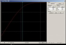
Reducing the rails to +/- 9V, required reducing the source resistance a few ohms to keep the output DC offsets low.
Simulated Data:
Bias Id = 6.35mA
Source 1kHz sine
X0(Hz) THD(%) DC offset (uV)
40 0.000 14
120 0.003 25
200 0.009 86
400 0.032 324
Source 10kHz sine
X0(Hz) THD(%) DC offset (uV)
40 0.000 11
120 0.003 45
200 0.010 92
400 0.039 400
Slightly higher DC offsets in the higher frequency sim. But very small, uV.
THD increasing with fo.
I will try with different bias for Id (Need to see the curves on the datasheets) and "white follower" topology to see if the THD lowers. So loading is a little bit of a factor at the higher XO frequencies.
More info later.
Attachments
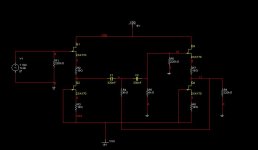
Here's the prototype:
Lowered THD @ 400Hz. Calculated 0.001% with 1V peak input sine. Reduced the filter Capacitance to lower loading and distortion.
White follower not needed since it can drive this load okay
Cascode topology doesn't need to be called in since it's a lower frequency XO range.
Specs:
Solen Film and Foil Polypropelene Caps
Matched JFETs
Metal Film Resistors
Well, that's it for a while. Can't build anything till next month. Out of town.
Attachments
Last edited:
X/road
So, I've been living with these for awhile now, and they really sound great. However, there are probably some tweaks that can make them sound better.
Q: Which is preferred?
a) A BSC circuit
b) High Q HP filter for the FR
Q: Which is preferred?
a) A passive circuit at the speaker, which can effect the speakers response (quoting Linkwitz)
b) A passive buffered circuit which has caps and/or coils in the signal path?
Q: What relationship exists between stiffer damping at the terminus and cone excursion?
Thanks
- Status
- This old topic is closed. If you want to reopen this topic, contact a moderator using the "Report Post" button.
- Home
- Loudspeakers
- Full Range
- Tysen Variation FE167E with CSS SDX7