Hi all,
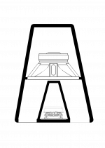
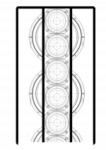
inspired by @wesayso's twin towers I came to the following concept: pictures in the next two posts.
The main use would be for sound reinforcement in (old) churches with the main aspects on unobtrusiveness, narrow vertical dispersion and, of course, very balanced sound. I don't have one specific church in mind, we have so many in need of at least bearable sound...
Speakers should be 9x Mivoc AW2000 and 25x Vifa TC9FD; active X-over, filters and amps in the enclosure.
I'm looking forward to your comments!
Last edited:
I'm fully aware that woofers and full range section have to be digitally time aligned, so apart from designing the optimum cabinet the "plate amp" will be a major concern. Optimally it should connect as well analog as digital, XO and filters controllable via ethernet, power 1x800W RMS @4Ohms and 1x500W RMS @8Ohms. Definitely nothing to be bought off the shelf...
Cute project! Did you sim the enclosure sizes? to see where you'd cross over the TC9 array to the bass line? Do look at actual impedance plots of drivers in enclosure with that trapezium shape. It might need some padding on the (internal) side walls next to the drivers.
Another question, would this array be standing on the floor or hanging up at a certain height? The reason I ask is the line array behaviour (response falling off -3 dB for every doubling of distance) would stop at the array length/height. Having it on the floor would make it behave like a longer array. In a church you probably won't get any help from the ceiling.
Also look at Jim Griffin's paper to see more detail about near field to far field transition.
My arrays are primarily near field, in a bigger room you'd listen in far field depending on array size.
Cute project! Did you sim the enclosure sizes? to see where you'd cross over the TC9 array to the bass line? Do look at actual impedance plots of drivers in enclosure with that trapezium shape. It might need some padding on the (internal) side walls next to the drivers.
Another question, would this array be standing on the floor or hanging up at a certain height? The reason I ask is the line array behaviour (response falling off -3 dB for every doubling of distance) would stop at the array length/height. Having it on the floor would make it behave like a longer array. In a church you probably won't get any help from the ceiling.
Also look at Jim Griffin's paper to see more detail about near field to far field transition.
My arrays are primarily near field, in a bigger room you'd listen in far field depending on array size.
Thanks for looking in - will come back to you in the late afternoon (have to leave now).
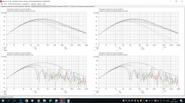
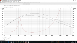
I got interested in using the Mivoc AW200 as sub so I made a sim in BOXSIM.
8 pcs (9 is an odd number to wire, whereas 4 in series and paralleled with another set of 4 makes 8 Ohms) AW 200 in a 200cm high enclosure 12.5 liter pr. unit.
Looks quite promising.
Of course you need some heavy EQ on the subs. but placed near corner you should be able to have a good low end extension.
Attachments
Interesting layout, looking at it I had a few thoughts. Depending on where you crossover you might get a directivity mismatch as the woofers are mounted in a short horn with a narrow profile. The TC9's are in front and will have pretty wide horizontal dispersion.
Had you though about using a compression chamber in front of the woofers and letting them exit through ports?
If you want narrower horizontal directivity you could put the same angle on a waveguide/horn in front of the TC9's to get a better match.
I would use Hornresp to get an idea of what will happen to your woofers response in the different configurations.
@wesayso:
No, I didn't do any sims yet, this is still an idea. Padding will definitely be needed, thanks to you and fluid I have some good information which way to go.
The array is intended as a floor-stander, flying it would be a no go in most old churches. Thanks for the Griffin link, will give it a close look.
@koldby
Thanks for simming the Mivocs! The 12,5 liters/unit are a good place to start with")
The 3 by 3 were my first idea wiringwise.
The arrays should be places in corners where possible, otherwise EQ has to help with low end.
No, I didn't do any sims yet, this is still an idea. Padding will definitely be needed, thanks to you and fluid I have some good information which way to go.
The array is intended as a floor-stander, flying it would be a no go in most old churches. Thanks for the Griffin link, will give it a close look.
@koldby
Thanks for simming the Mivocs! The 12,5 liters/unit are a good place to start with
The 3 by 3 were my first idea wiringwise.
The arrays should be places in corners where possible, otherwise EQ has to help with low end.
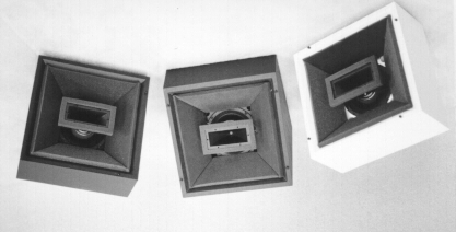
your idea sort of puts to mind what a stack of these would be like
with respect to sound in churches it's always RT60 that's the problem.
The Fraziers are made for raster ceilings, AFAIK.
Of course it's RT60 - hence as narrow as possible vertical dispersion to keep sound away from (high) walls and ceiling.
Interesting layout, looking at it I had a few thoughts. Depending on where you crossover you might get a directivity mismatch as the woofers are mounted in a short horn with a narrow profile. The TC9's are in front and will have pretty wide horizontal dispersion.
The general idea was to have at least some control in low end dispersion, therefore the horn shape. The horn angle would have to be discussed still.
Had you though about using a compression chamber in front of the woofers and letting them exit through ports?
If you want narrower horizontal directivity you could put the same angle on a waveguide/horn in front of the TC9's to get a better match.
I would use Hornresp to get an idea of what will happen to your woofers response in the different configurations.
No, I haven't, but this could be a very good idea. Could you make a crude sketch how you mean it, please?
Alas, I'm absolutely new to Hornresp, but at least I have it installed.
The general idea was to have at least some control in low end dispersion, therefore the horn shape. The horn angle would have to be discussed still.
No, I haven't, but this could be a very good idea. Could you make a crude sketch how you mean it, please?
Alas, I'm absolutely new to Hornresp, but at least I have it installed.
The width of the mouth which is the horizontal dimension as you have drawn it will determine the frequency that the horn will have pattern control to. It takes a big horn to have pattern control at woofer frequencies.
The depth of the horn will usually dictate it's ability to load and increase spl.
The compression chamber is basically the air in front of the cone. This will create a bandpass response. The size of the chamber and the port size and depth will set the response.
It can be as simple as mounting the driver to a board face down and cutting a port somewhere in the cone area. Here is an example looking down. The hatched area is where the ports could be cut. Not to scale but gives you an idea.
You could simulate it as a front loaded horn by leaving the Vtc (Throat Volume) at 0 or bandpass by increasing Vtc to cone volume and Atc to the cone area. Ap and Lpt are the area and length of the port. You may need to double click on Tal to change these over.
The hornresp helpfile has a lot of information and there is a hornresp for dummies thread somewhere which is good to use to get an understanding of where to start.
It would probably make sense to start simulating one driver in hornresp rather than trying to go to 9 straight away.
Attachments
@fluid:
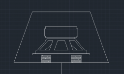
Meanwhile, thinking about your first reply, I came up with something that might resemble a pressure chamber for the Mivocs: (see attachment)
The drawing is 1:1, based on 12,5l per Mivoc and 1,5l per TC9.
Vtc would be roughly 1,92 liters.
Meanwhile, thinking about your first reply, I came up with something that might resemble a pressure chamber for the Mivocs: (see attachment)
The drawing is 1:1, based on 12,5l per Mivoc and 1,5l per TC9.
Vtc would be roughly 1,92 liters.
Attachments
Last edited:
TS params AW200
Just started to enter the TS params for the AW200 into WinISD and found out there are a lot of them not on the official data sheet. Where did you take yours from?
I got interested in using the Mivoc AW200 as sub so I made a sim in BOXSIM.
... AW 200 in a 200cm high enclosure 12.5 liter pr. unit.
Just started to enter the TS params for the AW200 into WinISD and found out there are a lot of them not on the official data sheet. Where did you take yours from?
Last edited:
I got it from the .PDF file on this page:Just started to enter the TS params for the AW200 into WinISD and found out there are a lot of them not on the official data sheet. Where did you take yours from?
https://www.mivoc.com/gs/product_info.php?info=p9_mivoc-aw-2000-8---20-cm--tieftonsystem.html
- Status
- This old topic is closed. If you want to reopen this topic, contact a moderator using the "Report Post" button.
- Home
- Live Sound
- PA Systems
- Two-way line source for church sound