It has nothing to do with PP or SE, nor has it anything to do with claiming anything.
Just like you came up with an example, I came up with an example showing that bifilar winding is not necessary per se to reach enough HF bandwidth, also for "difficult" high Rp tubes.
Check this thread (post #64) for Gary Dahl's experience with my PP IT for 6SN7 (Rp 7k!) driving PP 300B output; it reaches 100 kHz and is not bifilar wound. So it can be done.
Last edited:
Check this thread (post #64) for Gary Dahl's experience with my PP IT for 6SN7 (Rp 7k!) driving PP 300B output; it reaches 100 kHz and is not bifilar wound. So it can be done.
Yes, I was interested in that post. I was hoping to see some measurements as well, specifically phase balance on each push/pull output as frequency is ramped. It was Lynn who on his personal website suggested the lissajous pattern test as a good indicator of balance, and I had very eye-opening results when I did this test. There is an old thread, probably 8 years ago, where I published some results on this site. This was well before MM was offering their bifilar transformers, and a time of great frustration for me. From what I hear Gary has a good ear, being a musical person, so if he says it sounds good I don't doubt it, but I would still like to understand the objective performance of the design. How does it perform at various signal levels, frequency, grid current, etc?
Once everything gets summed in the OPT, it can be reasonably easy to get a frequency response at the speaker terminals that looks pretty good, which I found when using Onetics and Lundahl IT's. But combining this with consideration of distortion and output level, things begin to show as compromised. It is my understanding that because of the phase shift aberrations going on between the push/pull pair, distortion enters into the summed product (in fact, you can see distortion on the push output, and distortion on the pull output). Do they add together to be distortion-free? Possible, but it would surprise me. It may even be reasonably pleasing to the ear regardless, since our ability to hear distortion of high frequencies diminishes rapidly (heck, I can barely hear a movie on the big screen these days, my age is showing).
Perhaps some of this is an exercise in theory, if we can't really hear the distortion of 15 kHz, I'll give you that. Does anyone really care about 5W and 10W outputs of 15 kHz? Is that a reasonable expectation? But my curiosity was sparked heavily when the measurements confirmed what I was hearing, and as best as I could determine the IT was my limiting factor. Supposedly the Onetics was custom built for the application (Rp) as well, but it was the poorest performer.
Which leads to another thought along the lines of custom vs off-the-shelf products. The bifilar transformer (again, within its voltage limitations) I found to work very well with triodes ranging from 700 ohms to 2000 ohms Rp, which is a pretty wide range. You can use 7119/7044, EL34, 6W6, 45/46, 6n6p, etc.
I honestly never bothered to even try the SN7 - I gave up on IT with that tube long ago, and only ask it to provide near-perfect amplification into easy loads, capacitors or not, just avoid the iron. When trying to improve my PP IT builds, I received numerous suggestions that I 'wasn't using the right tube'. Go lower in Rp, higher in gain, add zobels, etc etc. I don't need to request a custom transformer when going bifilar - it appears very compatible with just about any reasonable triode suitable to drive a 300B with a bit of grid current (my personal design criteria/requirement).
If I am shoehorned into a custom transformer, how sensitive is it to tube aging, or side/side matching of triodes? Again, I have not found the bifilar design to be highly sensitive to matching, which is a great benefit to having to purchase already-expensive 46's. I do try to match bias conditions to keep DC current well balanced, which helps the IT, but that isn't too terribly difficult to batch out.
Just some random thoughts, rather than a statement about right/wrong. If anyone wants to toss a transformer at me, I would be more than happy to run it through its paces and see how it behaves. Always looking for another suitable source of components.
As a side note- I bought Pieter's amorphous input transformer for the same amp, and it was crazy-perfect in both gain and phase balance, way past 100 kHz. Completely different application, of course. But I know Pieter can build a transformer. Never tried his IT's.
You really have no idea of the issue here. It's not JUST about frequency response but effective HF load and balanced phases. Or did you miss my conclusion about the LL-1635 in PP drive? Read it again at least....It has nothing to do with PP or SE, nor has it anything to do with claiming anything.
Just like you came up with an example, I came up with an example showing that bifilar winding is not necessary per se to reach enough HF bandwidth, also for "difficult" high Rp tubes.
What should I check? I can't see any REAL measurements. It can be done in words for now. For real I haven't seen it, yet....when I see it I might change my mind! It works like that for me, sorry!Check this thread (post #64) for Gary Dahl's experience with my PP IT for 6SN7 (Rp 7k!) driving PP 300B output; it reaches 100 kHz and is not bifilar wound. So it can be done.
As a side note- I bought Pieter's amorphous input transformer for the same amp.....
Actually these input transformers have Finemet (nanocrystalline) toroidal cores, not amorphous.
Oh I forgot one important thing. A bifilar transformer requires LESS time to be made in comparison to another one with singles layers for the simple reason that I make 2 turns per time straight away, if one is well organised. So nearly half time to make it which means MUCH less cost (and/or higher revenue). Big difference for serious business!
So please don't tell me it is not necessary. It's just subjective opinion.
So please don't tell me it is not necessary. It's just subjective opinion.
Oh I forgot one important thing. A bifilar transformer requires LESS time to be made in comparison to another one with singles layers for the simple reason that I make 2 turns per time straight away, if one is well organised. So nearly half time to make it which means MUCH less cost (and/or higher revenue). Big difference for serious business!
So please don't tell me it is not necessary. It's just subjective opinion.
You are not forgetting, but echoing what I wrote in post #108

I just finished a series of IT's for EML20B, but instead of bifilar I wound them layer for layer P - S and so on. Very tight coupling and very low leakage inductance. Almost as much capacitance as bifilar. A bit more work
You are not forgetting, but echoing what I wrote in post #108
So I am right. Thanks!
Yes, you are right with the amount of work.
So more time, more expensive, but finally counts what the winder charges, right?
It depends on how you see it and run the business. So you can't say it is not necessary. It's subjective...
Perhaps some of this is an exercise in theory, if we can't really hear the distortion of 15 kHz, I'll give you that. Does anyone really care about 5W and 10W outputs of 15 kHz? Is that a reasonable expectation? But my curiosity was sparked heavily when the measurements confirmed what I was hearing, and as best as I could determine the IT was my limiting factor. Supposedly the Onetics was custom built for the application (Rp) as well, but it was the poorest performer.
Two things.
1) HF THD might re-enter the audible range into another form.
2) There certainly are instruments, especially brass type, that do have a rather powerful and extended ultrasound spectrum. The thing is that referring the listening experience to just the physiological hearing range is reductive. The human body is really full of all sorts of receptors with wider "frequency range" that do have an impact on the emotional state. Easy example: Just think about the proven benefits of music for babies in their mum's belly....
Regarding input transformer I have found it easier to solve. I must say that however I don't use vacuum tubes at phono and line level as for me SS class A works better. So it's tube power amp or tube integrated amp "at worst". The input transformer, when I use it, is usually the one that defines (or heavily impacts on) the overall FR in my amps. This way, with the right choice, IT never shows its limits if behaves ideally in that range. Still more than good enough for me, like 75-90 KHz F3.
It all depends on goals. I've heard most of the "classical" tube topologies and don't care for them ... Williamson, Dynaco, Mullard, Acrosound, and the other variants of popular 1950's designs. I came to the conclusion, perhaps wrong, that the coloration I was hearing was coming from the phase-splitter, and since I was starting out with zero-feedback amplifiers, why not try an interstage transformer?
Modern transformer design has gone a long way since IT-coupled amps were abandoned in the late 1930's, so why not? When I started with the Amity in 1997 or so, the only choice was the Lundahl 1635 or 1660, so I started with the LL1635 and a very simple two-stage design (input -> 5687 -> LL1635 -> Vaic VV32B/300B -> good OPT).
It sounded very different than any PP amplifier I'd ever heard, while measuring flat from 30Hz to 20 kHz, and had pretty low distortion, below 0.5% at 16 watts. That was my main amplifier from 1997 through 2005 or so.
The idea of a 3-stage amplifier using a simple SE input stage, a phase-splitting transformer, then a PP 45 or 2A3 driver stage, IT, then PP 300B was tried, but I was never satisfied with the sonics or the questionable phase-balance of the SE -> PP transformer. It's one thing for a line-level input transformer, but quite another for a transformer that has to carry DC on the primary, split phase, and then deliver a substantial voltage swing to the opposed 45 or 2A3 grids. Maybe it's possible, but I lost interest, since the first stage has the least to do of all the parts of the amplifier.
The Karna project went much better. The input transformer can be any good-quality 1:1 (with resistor balancing) or a 1:1+1 input transformer, while the real bottleneck remains the first interstage. If pulse response is the primary criteria, well, a DC-coupled transistor amp with ample feedback wins that contest, whether it's Class A or Class AB. Conventional PP-pentode-with-feedback amplifiers are a distant second, but 70~100 kHz bandwidth is within reach if the output transformer has well-defined phase performance in the 50~200 kHz region.
Returning to Karna variants, the bandwidth of the overall amplifier is largely determined by the first interstage. A simple RC-coupled first stage gets around the problem completely, and can drive the 45 or 2A3 grids without issues, since only 20V peaks are required per side ... little more than a powerful line driver. Other solutions are LC-coupling, either with a center-tapped inductor or paired inductors for each input-tube plate. Both solutions require a lot of inductance and low capacitance to ground for adequate bandwidth.
The amplifiers I'm listening to right now have O-Netics (Bud Purvine) 1st and 2nd interstage transformers, which sound really good but also get pretty wild above 25 kHz. I prefer them to the much better-measuring Lundahl's, and will be installing the new Tribute/Pieter 6SN7 interstage in the near future. This should give a simple option of either 6SN7 or 5687 input tubes, each with different bias points and plate voltages.
Returning to the original point, the least essential transformer in the circuit is the first one. All the other transformers have an important job to do.
* The input transformer breaks the ground, which eliminates any possibility of a ground loop, filters off RFI, rejects about 80 dB of common-mode noise (whether using the RCA or XLR inout), and also splits phase for unbalanced inputs. The cost saving between a SE and PP input section is trivial, so there is no real advantage for a SE input section.
* The 2nd interstage allows Class A2 and AB2 operation, since the 45's can drive the 300B grids about 20V positive while retaining low distortion (distortion rises from 0.2% in pure A1 to 3% in pretty deep A2). I've seen no evidence that A2 or AB2 harms the 300B tubes. The 2nd interstage also delivers a symmetric drive to both 300B grids, irrespective of the AC balance of the preceding driver stage, and the full linear power of the preceding stage is available when one of the 300B grids goes positive. The independent B+ power supplies also insure that when the output section clips, the rest of the amplifier is unaffected. The independent B+ power supplies also insure that the quite distorted current modulation arising from balanced operation does not reach from one section to another.
* The output transformer is of course necessary so adequate current can be delivered to the loudspeaker voice coils.
Zigzagflux,
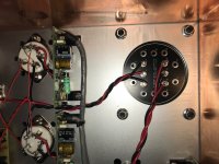
May I ask how you connected your Monolith IT in detail ?
This came with them:
So, when in your schematic the triodes at the top of the push pull are "1" and the triodes at the bottom are "2": Did you connect the anode of your 46(1-upper system) to 14 and the grid of the 300B (1-upper system) to 2 ? Is this the way ? This is how I would read the text, but the drawing from the colleagues of Monolith next to the table is confusing me a little bit.
May I ask how you connected your Monolith IT in detail ?
This came with them:
An externally hosted image should be here but it was not working when we last tested it.
So, when in your schematic the triodes at the top of the push pull are "1" and the triodes at the bottom are "2": Did you connect the anode of your 46(1-upper system) to 14 and the grid of the 300B (1-upper system) to 2 ? Is this the way ? This is how I would read the text, but the drawing from the colleagues of Monolith next to the table is confusing me a little bit.
Looks like we have different transformers. I am using the IT-02. For my setup, 2 and 6 go to each respective 46 plate, and the driver stage B+ to terminal 4.
On the secondary, 14 and 10 go to each respective 300B grid, with 12 going to the circuit common of the output stage.
Based on your hand sketch, it looks like the primary is described correctly (12 to driver B+, 10 and 14 to 46 plates). On the output stage, I would connect 1 and 7 to the 300B grids, and tie 2-6 together to circuit common.
Would be easy enough to test, to verify polarities are correct. You could run lissajous test to make sure you have the right bifilar windings identified; it will either be completely right or completely wrong, I would guess, not much room for interpretation.
Attachments
Strange...I got the ITA-02...it is defined as (1+1): (1+1), so I was not surprised to see two separate secondaries...by the way: Connection 4 in the table is a tab between the two secondaries actually...not sure how the drawing shall look like with tab 4, but I guess it is needed to be conncted, even when fixed bias with two secondaries are used ?
An externally hosted image should be here but it was not working when we last tested it.
Yes, they do.
But forget my comment aboit the fifth one...it is only in the text mentioned above, but not existent in reality...I connected stuff and it plays currently wonderful music...so I guess I did something right. I will post later my listening impressions, I guess we should give the Monolith now some hours to burn in...
this is now a cap-coupling-free chain ... hiphiphurray ! A lot less coloration for sure.
By the way: If I want to drive a SE-Outputstage with this transformer...? Paralleling the secondaries or just use one ?
Last edited:
2 and 6 are the terminals for the grids and you should follow that. Capacitances might not be the same if you use 1-7 and so FR. You can try....
Anyway, following instructions for 2 and 6 to the grids, 1-7 can be tied together with self bias or common neg. bias or stay independent if individual neg. bias.
Because the transformer is 1+1: 1+1 and fully symmetric one can reverse primary with secondary as in the case of zigzagflux...
For SE operation both primaries and secondaries would be better off in series, with the right phases. That's the IT-01 (with air-gap for 25 mA anode current) basically. Otherwise you will get 62.5H only which is less than the IT-01/25mA.
Less inductance = less headroom and/or more distortion at low frequency. High frequency might be worse with windings in parallel as well but it depends from case to case.
Of course, because the IT-02 has no air gap (except the tiny natural gap which can handle about 2 mA) it is only for PP and you can only use it in parafeed for SE drive.
45, thanks for your advise...but just to be precise: I would continue to use the IT-02 at its primary with the same push-pull driver for the moment...so even without an airgap it should be fine. The idea was more to work step by step back, so the power tube only would run in SE to figure out
A. Can a SE stage only drive my speakers...different DHTs to be tried, not just the 300B, but as well some Vaic VV520, Gm-70, 814 and 813 in triode, 845 etcetc. I got quiet a bit of OPTs in SE for this comparison.
B. How will SE change the sonic presentation when the driver stage is more or less exactly the same, so it is not a different design/setup/ components, but really the concept itself which you compare, or as Lynn said somewhere: Only one step at a time, or you will never figure out what is going on.
That was the idea behind my question...so primary setup stays with push-pull, no air gap needed, but the secondaries either need to be connected in parralel or you use only the upper half I guess...
It is SE to SE or PP to PP. This is the same limitation the LL1635 has that's why I will cheat driving the transformer with a concertina to get PP drive from a SE.45, thanks for your advise...but just to be precise: I would continue to use the IT-02 at its primary with the same push-pull driver for the moment...so even without an airgap it should be fine. The idea was more to work step by step back, so the power tube only would run in SE to figure out
- Status
- This old topic is closed. If you want to reopen this topic, contact a moderator using the "Report Post" button.
- Home
- Amplifiers
- Tubes / Valves
- Two driver options for 300B push pull