Hi Zigzag,
I am following you slowly...I tested the input/driverstage of my e182cc/el34 amp (now in triode): So I plugged in a LC instead of RC using LL1668pp, CT gets B+ to the LTP-anodes of the e182cc followed by coupling cap.
No matter what I do, RC sounds more resolving, more air (coupling cap is always the same).
Not sure if this correspondes with your impressions as well or if this is only this specific anode choke.
By the way: How did you heat the 46/300B ?
In my line-stage I just changed from 4p1l to 801A using coleman-reg this was quiet easy. Nevertheless I would like to see if other heating options exist, how they sound etc.
As I use differential pair with OPT in the line-stage: Is not even AC-heating feasable ? So, initally Ac-Hum-pot per tube and than cancellation in the OPT ?
I came across this article where Steve Bench explained a way how to get AC-Heating quiet Effects of AC Heating Power Applied to Directly Heated Triodes
Last edited:
Hello Blitz,
Glad to see your experiments continue. It was years of experimentation for me. That's the fun of diy; you can decide when it's time to stop, or when it's time to try a different method.
Over the years, I went from DC voltage heated to AC voltage and then to DC current heated. Combinations of both direct and indirect stages. My experience has been if using indirectly heated tubes, there is no point in using DC heating of any kind as long as you are diligent about construction. Twisted pair, careful routing, biasing with DC voltage will all permit a noiseless heating solution, so much so that I cannot detect any noise or hum when measuring with my sensitive soundcard. My input stage with SN7 is AC heated, absolutely zero hum or noise.
Contrary to many other's experience, I have not found a huge difference in performance between DC voltage vs current heating with DHT's. Currently I am using current heating, but not because it is the ultimate and only correct solution.
What I can testify to is that in PP amps, AC heating with DHT's can be done. I had a 46 PP stage followed by a 300B PP stage, all AC heated. Output at speaker could be trimmed to less than 1 mV, which is pretty darn impressive. However, when looking at the spectrum of hum, it was pretty rich in harmonics and 'sludge'. I can't say that I actually heard a negative effect; I just knew it was there. IMD products may be relevant; I did not measure them with that version of amp. But I was happy with it.
By far the greatest bang for the buck for me was resorting to a bifilar interstage transformer to drive the final output stage. Like a factor of 10 more important than selection of capacitor, selection of heating method, selection of tube, etc. Other than possibly playing around with a MOSFET driver someday, I won't drive my 300B by any other method.
Smile...my Monolith IT is sitting here as well waiting for its first run...same one as you have...I did not immediately plugged it in as I want to use this as a learning experiment going from RC to LC to CCSC to IT finally and listening what is doing what...
...on the heating, well I chose the current reg route of Rod Coleman as I wanted to have a solution which for sure will do the job...but man the heating psu becomes very fast very complex, especially if you use multiple dht stages. I found that LCLC before the regs makes a nice improvement...I will test a pure passive DC-supply without regs next. Kind of Thomas Mayer approach (vinylsavour) and will compare.
...on the heating, well I chose the current reg route of Rod Coleman as I wanted to have a solution which for sure will do the job...but man the heating psu becomes very fast very complex, especially if you use multiple dht stages. I found that LCLC before the regs makes a nice improvement...I will test a pure passive DC-supply without regs next. Kind of Thomas Mayer approach (vinylsavour) and will compare.
Hi all, Gary Dahl pointed me to this thread ... sorry about the very late contribution, but better late than never.
The purpose of the shunting resistor on one of the VR tubes in the stacked pair (which deliver 300V of shunt-regulated voltage) is the initial turn-on condition. If the resistor is not there across at least one of the VR tubes, neither might fire on turn-on. The small shunt resistor provides voltage to one of the VR tubes, and once it fires, the starting voltage then appears across the other VR tube, as well. This is mentioned in passing in the old literature.
As for the sonics of a long Zener-diode string (using Zeners selected for low tempcos) vs a classic VR tube, I don't know. Some VR tubes are prone to weird oscillations, and they don't like capacitive loads (no bypassing them with caps larger then 0.1uF). There are Zeners with tempcos near to zero, and these (in a long string) would be an alternative to a VR tube (although not as pretty). Sonics? Good question. If a single Zener has issues with nonlinear capacitance and other assorted solid-state colorations, it seems like putting a lot of them in series might reduce that ... the capacitances would be in series, after.
However ... the sonic comparisons I did with Gary Pimm many years ago, comparing a variety of current sources (used as plate loads) was not a happy experience. I was dismayed they all sounded different, and many had a noticeable "solid-state" sound with associated "grit" and flattening of tone colors. The cascoded-MOSFET approach used by Gary Pimm had pretty much no tonal coloration, although I still had a very minor reservation about just-perceptible dynamic flattening. The typical current source with a circle-of-two bipolar transistors was surprisingly audible, and in my personal impression pretty much wiped out the triode sound. However ... this impression would be very much listener and speaker-dependent. I can imagine many systems where it wouldn't be audible at all.
By contrast, choke loads and the better-quality transformers result in a more vivid, more colorful sound. This could be an artifact of strange HF phase shifts or LF behavior of the iron core, but it's pretty obvious if the choke or transformer is below par ... the sound is grossly colored and bandwidth suffers, a sort of not-good vintage sound. The best chokes and transformers sound almost the opposite ... more dynamic, not less, and tone colors are more vivid compared to RC-coupling with average-quality caps.
Is this enhanced vividness a coloration? Hard to say. I really don't know. It's like comparing a really good horn system (that has flat response and good impulse response) to a really good direct-radiator. They just sound different, even if the measurements are similar. I suspect low-level energy-storage mechanisms, but that's just a guess.
Pieter has sent me an interstage transformer optimized for 6SN7's working in push-pull (with a Zout of 15 kohms), and it has an astounding bandwidth of 100 kHz. Gary Dahl has been using it for the last several months and is very, very happy with the sound of his Amity amplifier (PP 6SN7 input/driver -> Pieter's interstage -> PP 300B's).
I have a zillion other projects (including a new speaker to replace the Ariels), but do plan to convert my Karna amplifiers to Pieter's interstage, which then lets me swap the input stage from a 7119 to a 6SN7 (I much prefer the distortion signature of the 6SN7 family). I like the sheer simplicity of ZigZagFlux's amplifier, and my neighbor Thom Mackris' new amplifier (the NiWatt) with all-RC-coupling sounds really good to me. Thom's NiWatts are an updated derivative of the classic Reichert Silver 300B's, but with choke loading for the 6SN7 driver section, fully independent B+ supplies for the 6SN7 input+driver section and the 300B output section, and a copper subchassis for the audio circuitry.
So I'm not as doctrinaire about cap-coupling as I used to be when I first designed the Amity and Karna amplifiers. The biggest gains seem to be fully isolated B+ supplies with independent transformers, damper-diode rectifiers, and choke filtering.
P.S. I don't know if I've said this elsewhere, but I got to audition Allan Wright's PP VV32B amplifier against my personal Karna amplifiers at one of the last VSAC shows in Washington, around 2003 or 2004 or so. Allan was a guest at my house in Silverdale, and of course he brought his brand-new PP VV32B amplifier with him to demo at the VSAC. The comparison was ... well ... interesting. My amps had decent-quality but not awesome Chinese (or Russian) 300B's, adequate but not amazing, while Allan's amp had a stupendously expensive quartet of matched-and-balanced VV 32B's.
I expected Allan's amps to wipe the floor compared to mine, considering the output section cost about three time as much. I've used VV32B's before, and they are noted for their super-vivid tone colors and stupendous dynamic range (thanks to insane peak currents and very linear operating region). Yes, they're kind of microphonic, but I can listen around that.
I was surprised that Allan's amps, despite the heavy 85 mA operating current for each VV32B, sounded tonally thinner and more dynamically curtailed compared to the Karna PP 300B. The Karna's had the usual lush-but-transparent 300B sound with all the advantages of PP dynamics. Allan was visibly dismayed, although he said nothing. I was kind of shocked, myself, and didn't expect what I heard. His amps weren't more "accurate"; they were just thinner and more bass-shy, despite the superior performance of the VV32B's (which are super-lush and super-dynamic).
I never talked to Allan about it, but my best guess was the shared current source that tied together the VV32B "cathodes" was seriously limiting the current drive of the output section. I did urge Allan to at least try bypassing the current source with a good-quality capacitor, which in effect would convert the amplifiers to plain old PP drive, instead of a differential amplifier, which is what they were. I'm not sure if Allan tried that or not, and sadly, he's no longer with us.
My takeaway from that unnerving (and socially difficult) listening session is that differential amps are not necessarily a good solution for audio ... and more suprisingly, that classic Class A PP is very different sounding than differential. The currents do flow in a different way, after all, and classic PP is a parallel circuit while differential is in series. This probably has implications for distortion spectra as well as dynamics.
Last edited:
On a related topic, the sonics of different phase splitters in "traditional" PP amplifiers have interested me for a long time. My subjective preferences put the (very common) split-load inverter at the bottom, the Mullard long-tail differential circuit in the middle, the old-fashioned (and very much out of favor) floating paraphase near the top, and transformer coupling at the top. The biggest subjective differences seem to be vividness of tone color and dynamics.
I note the least-favored versions are working differentially, or at least in series. Put another way, the first two circuits run out of current gain all at once, with distortion appearing at both output terminals. The last two circuits have one section run out of current while the other section steams along without a problem ... they work in parallel, not in series, unlike the first two circuits. (The floating paraphase samples the AC voltage of the upper tube, but it doesn't draw current from it to any significant degree.)
The (perhaps misguided) idea behind the Karna was an amplifier where the transformers restore balance at each stage of the amplifier, and the opposing side of the circuit is available to supply current when the other side runs out of current ... pure Class A PP operation at every section, with high peak current delivery in all modes of operation, and more important, linear current delivery for all parts of the duty cycle. No Class AB on-off transitions at the zero-crossing, no current starvation at the wave tops and or into a reactive load, and lots of current even in peaks that enter Class A2 or if one side cuts off completely. Differential amps can't do this, and Class AB amplifiers are effectively two SE amps that alternately switch back and forth with a narrow combined Class A region.
Last edited:
Series or Parallel
Lynn
I thought the classic PP output stage was Series whilst the Circlotron output is an example of Parallel. The differential approach i.e. Allen's amp is the same configuration of supply and transformer as Series classic PP, only difference is the cathodes are tied together by a current source.
Regards
Ejam
Lynn,
thanks a lot for taking the time to share your experiences and updates...comparing your driver-setup with my current differential pair-driver setup is high on my todo-list, but with kids you have a bit slow moving on DIYaudio...so I just got ready to change the El34 to 300B next weekend, again with Coleman regs, which is like building an own amplifier.
It is a pitty that Gary does not offer any pcbs for his current sources anymore...I would be very happy to build some of those you use and compare to those from Kevin Carter I have on hand.
One question on the Karna: I saw a 10ohm resistor on the input section/secondary of the IT of the 45-section and than a second 2,5v AC-Winding going to T1 and T2 with balancing poti ? Can you explain this a bit more, please ?
One question on the Karna: I saw a 10ohm resistor on the input section/secondary of the IT of the 45-section and than a second 2,5v AC-Winding going to T1 and T2 with balancing poti ? Can you explain this a bit more, please ?
The filaments/cathodes of the driver and output tubes are AC heated. The 2,5V AC / balancing pot at the input of one of the driver tubes is there to "inject" some AC when necessary to balance out and make the amp as quiet as possible. I built a Karna with Rod's regulators, and then you don't need the balancing act.
Hi Pieter,
Thx a lot...well, I have built now one set of raw supplies and four reg for the 300B and as considering to use AC-heating for the 45 section to reduce built complexity...
Please let me know if there is a chance to get a set of your IT for this project...
All the best
Thx a lot...well, I have built now one set of raw supplies and four reg for the 300B and as considering to use AC-heating for the 45 section to reduce built complexity...
Please let me know if there is a chance to get a set of your IT for this project...
All the best
Lynn
I thought the classic PP output stage was Series whilst the Circlotron output is an example of Parallel. The differential approach i.e. Allen's amp is the same configuration of supply and transformer as Series classic PP, only difference is the cathodes are tied together by a current source.
Regards
Ejam
It's easy to distinguish series from parallel by doing a little thought experiment. What happens if one tube (of the pair) is removed from the circuit? (Ignoring DC balance issues, just looking at the audio signal.)
In a series circuit, output drops to zero, since the paired tubes are in series, just like old-school Christmas tree lights. This is also what happens in a differential circuit, or a circuit with a shared current source between the cathodes.
If one tube clips or drops to zero conduction, the output is hard-clipped. The circuit has a maximum current and that's it. The limit is a hard one, set by the current source. Adding feedback to the circuit merely makes hitting the limit even harder.
In a parallel circuit, output drops, but only by a few dB, since one tube is still working just fine. It merely reverts to SE operation, with a distortion profile of a SE amplifier.
A PP Class A circuit with traditional cathode bias will operate as a parallel circuit until the cathode-bypass capacitor is discharged, in about a half-second, depending on current draw. It then slides towards a more differential mode of operation, and peak output current capability drops.
Fixed bias sidesteps that problem, at the expense of needing to monitor the quiescent bias in each tube every now and then.
The filaments/cathodes of the driver and output tubes are AC heated. The 2,5V AC / balancing pot at the input of one of the driver tubes is there to "inject" some AC when necessary to balance out and make the amp as quiet as possible. I built a Karna with Rod's regulators, and then you don't need the balancing act.
I now see the AC injection as a mistake, and will be comparing DC heating (in both 300B and 45 sections) to more traditional humpot-balanced AC in the near future.
Although I've found issues with various DC heating schemes in the past, I'm a bit more open-minded now, and will be trying the Thomas Meyer choke-filtered DC approach in the near future.
One very real attraction of well-done DC heating is getting rid of hum modulation, which is a form of AM modulation resulting from small changes in gain caused by the heating and cooling of the filament at a 100/120 Hz rate. The 100/120 Hz IM sidebands are pretty far down, in the -60 dB range, but getting rid of it should result in more open sound.
The other issue with filament heating (AC or DC) is that small changes result in pretty noticeable changes in the sonics of the DHT. I had an external source of very pure AC (one of those regenerator gizmos) and adjusting the 300B filament from 4.2 volts to 5 volts resulted in a very different sound ... from mushy and dull, to rich and vivid, to sharp, and then aggressive and forward. All by making small adjustments in the heating voltage. Kind of similar to adjusting VTA in a phono cartridge .. one pretty obvious "right" setting (and it wasn't 5 volts) and the other settings pretty colored.
Last edited:
G'day Lynn,
I've built both your and Allens output stage to my amplifier and preferred by quite some margin the CCS tail.
I did use Gary's self biased v5 CCS in the tail and was able to adjust individual bias via twin pots in parallel under the CCS (DC and no AC, so not in the signal path), wiper to individual grid return, yes split secondary windings.
This was with a SE front end with high level transformer to PP grids, sounded great !!.
One day I removed the IT and paralleled the OP tubes into 1k6 OPT, DC coupled the drive to the OP tube. Vivid.
I always enjoyed reading your posts, please stick around for some.
Kind regards,
Hanze
Attachments
I performed a number of tests with the 2.5VAC hum-canceling pot trick. It did allow one to reduce the overall 60Hz hum at the output of the amplifier, typically I could get just below 1 mV. What was left was 120Hz and as seen by the scope, it wasn't clean, but filled with harmonics. The hum would also drift with time, requiring (if you are anal about hum) consistent re-adjustment to keep hum that low.
Regardless of the signal present at the output of the OPT, you still had 60Hz present at each stage of the amplifier that was AC heated. At the time, all three of my stages were AC heated, so there was a lot of hum floating around the amp. Negating it at the speaker terminals was nice, but the reality was I had IMD products sneaking into the signal at each stage. Not ideal, so I would discourage its use if low hum and low IMD is your goal.
Finding this, I even tried developing an 8-bit pure sine-wave source synchronized to the AC line voltage. I was able to provide 8-bit phase shift as well. Stepped up to 120V, and it then provided the power for the heater transformer. Pure sine wave to get rid of some of the harmonics. By phase shifting the source, I could add an additional tweak to cancel the hum created by the ripple present on the DC power supplies to the amp. It was a simple thought experiment, realized with a fun little project. I believe Steve Bench attempted a similar project, but with a different strategy. While it was a further improvement to the hum viewed on the scope, it never addressed IMD to an appreciable degree.
Now that I have resorted to DC current heating, the hum issue and its IMD is completely gone. A tiny bit gets through from the B+ power supply ripple, but not going to bother regulating a 300B push pull stage.
I might have mentioned this earlier in the thread, but regarding the difference between series and parallel stages, I found a simple assumption works well. If you design each stage ideally, it will never clip. You can accomplish this with input and driver stages, but likely not with the output stage. Go series for the first two stages for optimal fidelity. The output stage will benefit from parallel due to the likelihood you will push it too far someday. However, if you are confident that you listen at reasonable levels and are not looking for a party speaker, series can be a viable option. It's really personal listening preference. But those first two stages (at least in my Karna amp) do NOT clip or limit in any way; that output stage is begging for mercy by the time my driver stage feels any burden at all. So keeping fully differential for input and driver is optimal.
This thread has me thinking of common-mode feedback, or what Western Electric called the "Harmonic Balancer". I find it interesting that WE didn't use global feedback on their PP 300B amplifiers; they used common-mode feedback instead. Global feedback was reserved for their single-ended amplifier. And this was the research group that invented feedback only five years earlier.
A subtle advantage of common-mode feedback is that doesn't affect overall loop stability, although you still have to be careful that no common-mode oscillations are induced. More usefully, it reduces the most prominent and hard-to-remove distortion of Class A PP triode amplifiers: odd-order distortion. As is well-known, an all-triode balanced amplifier operating in Class A (not Class B) will, in principle, only have odd-order distortion (if perfectly balanced). Global feedback will reduce this, of course, but at the potential expense of loop stability.
Common-mode feedback is a different animal. It only affects common-mode gain and distortion, and has little to no effect on even-order distortion. It can, however, reduce odd-order distortion by 20 dB or more.
I have a particular interest in this since Gary Pimm and I found that nearly all the high-order (5th and higher) distortion in the Karna amplifier is coming from the input tube. Both the 45 and 300B have vanishingly low 5th-and-higher distortion terms, which I feel is a large part of their transparency. This was not true of any indirect-heated tube we tested; more seriously, there were 20 dB differences between vendors in the levels of 5th-and-up harmonics, and the harmonic profile only changed slightly (3 dB) with changes in operating current. We both felt the differences we saw were the result of subtle differences in internal construction, and not visible from the outside of the tube.
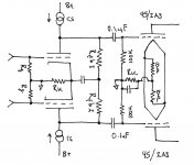
Looking at the schematic posted at the beginning of this thread, I noted the cathode bias setup for the input tube. In the current version of the Karna amplifier, I have an Ultrapath-style bypass cap between the center-tap of the interstage primary and the paired common cathode of the 5687/7044/7119 input tube.
If I adopted the RC-coupling shown in the previous schematic, common-mode feedback becomes an interesting option. Adjusting the Rfb resistors should alter the harmonic profile of the first stage, which after all is delivering 20V peaks to the 45/2A3 driver, so there's real voltage swing there.
Two options came to mind: two current sources, one for each plate, with independent feedback-sensing resistors. This is the lowest-distortion option, although there is a possibility of coloration from the current sources (we have different levels of obsession on this topic).
The other option is a more conventional RC-loaded input section, but with the paired Rload/Rfeedback resistors setting both AC balance and the overall level of common-mode feedback. Although overall distortion is somewhat higher (and headroom a bit lower), the harmonic profile could be different. If there are concerns about current-source coloration, it only appears in the common-mode output, which is mostly rejected in the following driver stage.
If Pieter is following this thread, I have a quick question ... are the interstage transformers you designed for Gary Dahl and myself suitable for use between the 45 drivers and 300B output section? That demands 80V peaks for each 300B grid, since the Karna is designed for A2 and AB2 operation, as well as the more ordinary A1 and AB1 modes. I expect the Zout of the paired 45's to be around 3k or so, and about half that is 2A3's are used (which I don't plan to do).
A subtle advantage of common-mode feedback is that doesn't affect overall loop stability, although you still have to be careful that no common-mode oscillations are induced. More usefully, it reduces the most prominent and hard-to-remove distortion of Class A PP triode amplifiers: odd-order distortion. As is well-known, an all-triode balanced amplifier operating in Class A (not Class B) will, in principle, only have odd-order distortion (if perfectly balanced). Global feedback will reduce this, of course, but at the potential expense of loop stability.
Common-mode feedback is a different animal. It only affects common-mode gain and distortion, and has little to no effect on even-order distortion. It can, however, reduce odd-order distortion by 20 dB or more.
I have a particular interest in this since Gary Pimm and I found that nearly all the high-order (5th and higher) distortion in the Karna amplifier is coming from the input tube. Both the 45 and 300B have vanishingly low 5th-and-higher distortion terms, which I feel is a large part of their transparency. This was not true of any indirect-heated tube we tested; more seriously, there were 20 dB differences between vendors in the levels of 5th-and-up harmonics, and the harmonic profile only changed slightly (3 dB) with changes in operating current. We both felt the differences we saw were the result of subtle differences in internal construction, and not visible from the outside of the tube.
Looking at the schematic posted at the beginning of this thread, I noted the cathode bias setup for the input tube. In the current version of the Karna amplifier, I have an Ultrapath-style bypass cap between the center-tap of the interstage primary and the paired common cathode of the 5687/7044/7119 input tube.
If I adopted the RC-coupling shown in the previous schematic, common-mode feedback becomes an interesting option. Adjusting the Rfb resistors should alter the harmonic profile of the first stage, which after all is delivering 20V peaks to the 45/2A3 driver, so there's real voltage swing there.
Two options came to mind: two current sources, one for each plate, with independent feedback-sensing resistors. This is the lowest-distortion option, although there is a possibility of coloration from the current sources (we have different levels of obsession on this topic).
The other option is a more conventional RC-loaded input section, but with the paired Rload/Rfeedback resistors setting both AC balance and the overall level of common-mode feedback. Although overall distortion is somewhat higher (and headroom a bit lower), the harmonic profile could be different. If there are concerns about current-source coloration, it only appears in the common-mode output, which is mostly rejected in the following driver stage.
If Pieter is following this thread, I have a quick question ... are the interstage transformers you designed for Gary Dahl and myself suitable for use between the 45 drivers and 300B output section? That demands 80V peaks for each 300B grid, since the Karna is designed for A2 and AB2 operation, as well as the more ordinary A1 and AB1 modes. I expect the Zout of the paired 45's to be around 3k or so, and about half that is 2A3's are used (which I don't plan to do).
Attachments
Last edited:
If Pieter is following this thread, I have a quick question ... are the interstage transformers you designed for Gary Dahl and myself suitable for use between the 45 drivers and 300B output section? That demands 80V peaks for each 300B grid, since the Karna is designed for A2 and AB2 operation, as well as the more ordinary A1 and AB1 modes. I expect the Zout of the paired 45's to be around 3k or so, and about half that is 2A3's are used (which I don't plan to do).
Suitable...hmm maybe but certainly sub-optimal.
The 6SN7 interstage transformers were optimized for the needed primary load impedance (high inductance!) while maintaining optimal HF bandwidth given the high Rp.
For a 45 interstage transformer the parameters are quite different.
What you're saying makes a lot of sense, Pieter. I can't begin to understand the extraordinary lengths you went in order to design and build a wide-bandwidth transformer that also operates with high impedances. Usually high impedances severely limit the bandwidth the transformer can provide ... and a source impedance of 15 k plate-to-plate is as high is things can get. The only other example I can think of are the old line-driver transformers that drove 600-ohm studio circuits.
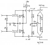
Returning to the previous post about common-mode feedback, an offbeat variant of both circuits is replacing the two fixed Rfb resistors with a single pot (Rfb pot), the Rk resistor with a pot (Rk pot), and then cross-connecting the two wipers with a high-value capacitor (in the 40uF to 100uF range).
The Rk pot sets the overall common-mode feedback level, and the Rfb pot sets AC balance (gain ratio between the paired input+driver tubes). You'd need a spectrum analyzer to set the pots: Rfb would control the level of even harmonics (AC balance, in other words), while Rk controls the odd-order harmonics (common-mode feedback ratio). It goes without saying the transformer will pass zero common-mode signal ... that's the whole point of balanced, transformer connections used for studio mike-feeds with long cables between the mikes and input console.
I was wondering if this strange little circuit could be applied to interstage transformers, but at first glance, the transformer pretty much shorts out any common-mode signal that the input tubes might create. Sure, there's a little, but the primary windings are only a few hundred ohms compared to the 6SN7 plate impedance of 7 k ohms. The common-mode signal appearing at each end of the primary should be pretty small ... at a guess, maybe less than a volt of AC signal, compared to 40V of differential signal.
Hmm ... food for thought there. Both RC-coupled circuits shown above, as well as the circuits at the beginning of this thread, generate a moderate amount of common-mode signal, thanks to various mismatches in the input and driver tubes. The common-mode signal is finally extinguished at the 45 -> 300B interstage transformer. If each stage is full differential, with current sources on the cathode end (which prohibits current sources at the plates), there's no common mode signal, due to the very high impedance presented to the paired cathodes.
Last edited:
Common-Mode Feedback Circuit
Lynn
You stated: "Returning to the previous post about common-mode feedback, an offbeat variant of both circuits is replacing the two fixed Rfb resistors with a single pot (Rfb pot), the Rk resistor with a pot (Rk pot), and then cross-connecting the two wipers with a high-value capacitor (in the 40uF to 100uF range)."
I get the Rfb part but the setup with the Rk pot? I see four versions here:
1. Two ends of the pot attached to the respective cathodes with the wiper to ground and the cap to wiper (ground), or
2. One end to the shared cathodes, the other to ground. The wiper to ground and the cap to wiper (ground), or
3. One end to shared cathodes, the other to ground. The wiper to shared cathodes and the cap to wiper (shared cathodes), or
4. One end to shared cathodes, the other to ground. The wiper to ground and the cap to shared cathodes.
Can you clarify please which version or is there another?
Thanks Lynn and Zigzagflux for pointing to DC-Heating...so I will follow your advise for the 45 stage...
I came across this document the other day: http://jacmusic.com/techcorner/ARTICLES/APP-NOTES/AN07-How-to-bias-DHT-tubes-without-mistakes.pdf
where Jac suggested strongly to use the artificial mid-tap created by two resistors even when DC-Heating is used.
I have just finished my 300B-stage with Coleman regs, so one raw-dc-power-supply and two regs (one for each tube)per channel. Rod advised me not to use the mid-tap-thing as his regs are absolutely quiet and this will lower impedance between tubes and mess up the 3D.
The only thing which I have still in the back of my mind: I did some experiments with my DHT-4p1l-DAC-stage, where the heaters have a physical mid-tap. Typically you use this to lower heater voltage from 4.2V to 2.1V. As I used them in LTP configuration, cathodes are connected.
I was astonished to realize that it made quiet a difference in sound how you connect the DC and the CCS. Many different combinations are possible:
- The positive side of the DC supply being either at the two 4.2V-Heater pins and the negative side at the mid-tap or vice versa.
- Then, the negative or positive side tied together and connected to the CCS in the tail.
In my setup some of the combinations sounded simply wrong and strange like if the phase of the speaker is messed up, diffuse, big mouthes of singers like if you have a big headphone on etc, while other combinations sounded very natural and 3D.
Best was: Negative sides of the heater regs tied together being connected to the mid-taps of the heater. Worst was positive side of the heaters to the 4.2pins and the ccs.
Soooooo: I learned that how to connect the DC-Heater matters a lot, at least in a LTP and when using the mid-taps of a tube to lower heater voltage. I guess it has to do with the physical layout of the tube and the resulting electron flow of the setup. That all was true for the 4p1l in 2.1V.
My question: How much of this should be considered with the 300B/45 ?
What Jac is describing is in my view not alone the point about hum, but as well the point about creating a symetrical potential between grid and cathode between the grid and the emitting surfaces inside the tube if you can follow me. So, the cathode and its signal is divided into two anti-phase signals, no ? Maybe I have a completely stupid thought here, than forgive me.
Last edited:
<cut>
Soooooo: I learned that how to connect the DC-Heater matters a lot, at least in a LTP and when using the mid-taps of a tube to lower heater voltage. I guess it has to do with the physical layout of the tube and the resulting electron flow of the setup. That all was true for the 4p1l in 2.1V.
My question: How much of this should be considered with the 300B/45 ?
Hello Frank, Yes the routing of the anode-current path for a DHT matters very much - with all DHTs, including the 300B, or 45.
Connecting resistors across the filament of a DHT adds a current-path which causes leakage of the signal (music) current, as well as the heating current. (Remember, one side of the filament is 5V higher than the other, and this slews the grid-bias, as well as the anode-cathode voltage. All along the filament, the bias, and so the gm of the triode is shifting - in total, at the two ends, you have a differential-signal across the filament).
Without yet offering a substantiating measurement, the subjective effect of adding shunt resistance - even of a value of multiple times the value of the filament's dc resistance - is readily observed as a diminished stereophonic image. It's a very notable difference (as you have witnessed), so if you are DC heating using high-impedance current-driven supplies, you can experiment with connexion points, and see. If you have a filament with a centre-tap, like the 4П1Л or the new EML variants, you can try that too.
Voltage regulation with typical IC regulators (LT1086, LM317, etc) does not offer much opportunity to experiment, because the filament is already shunted with the low impedance from the feedback loop, and the output capacitor. Their output impedance is very low below 1kHz, but then rises with frequency in an inductive manner, and this can lead to resonance with its output capacitor.
See, for example, the resonance-driven noise-peaks in these measurements:
Simple Voltage Regulators Part 1: Noise - [English]
The output impedance of the LM317 is treated in greater depth by Errol Dietz in an old EDN article, also reprinted in Bob Pease's « Troubleshooting analog circuits » (Butterworth-Heinemann 1991).
The signal-impedance of a smoothing choke is not sufficient to get the best out of the 300B, IME. A choke also adds leakage capacitance from its windings to ground, which is not helpful.
For most Regulated DC schemes, one side of the regulator has a higher leakage capacitance to the general circuit ground, and this also has an effect:
With my regulators and SE amplifiers, connecting the POSITIVE side to the anode-current return (i.e. to ground or a cathode resistor) usually works best; there are complications with PP stages that may make things different - so it's always worth trying different choices. But in every case, please check that the DHT is biased to the same current for comparisons, since the location of the anode-current return-node affects bias (Vgk).
What Jac is describing is in my view not alone the point about hum, but as well the point about creating a symetrical potential between grid and cathode between the grid and the emitting surfaces inside the tube if you can follow me. So, the cathode and its signal is divided into two anti-phase signals, no ? Maybe I have a completely stupid thought here, than forgive me.
If you are using voltage-regulated dc (as in Jac's diagram), there is little to be gained from changing the anode-current return-point. In this case, using the faked centre-tap will help eliminate noise and ripple (3-terminal regulators have plenty of that) and will be best. With my filament regulators, the noise level is in the low microvolt region, so added noise rejection is not required.
The symmetry that Jac refers to is that of the grid around the filament. This has a strong influence on residual noise - if the heating supply is noisy. It affects the signal current too - but that can be accounted-for by experimenting with the return-path connexion-point's location. Again - please compare each option to the 2-resistor centre-tap, and hear the difference.
The common-mode noise, due to transformer leakage capacitance (as Jac mentions) is an important consideration - see the current-loop indicated in Jac's diagram. This will cause common-mode leakage current if voltage regulation (or simple rectified dc, or passive-filtered) is used.
With my Regulators, both sides of the filament have series-pass transistors, to block noise-current from flowing in either side. The common-mode equivalent circuit has two transistor collectors in series - so the common-mode impedance for the leakage current is raised considerably. This is quite different to a voltage regulator solution, and means that the centre-tap is not needed, allowing you to use any anode-current return-path.
Leakage current can also be minimised if we choose a simple EI transformer with a split bobbin (= dual bobbin), for example: the Hammond 185 or 266 etc. These have such low leakage capacitance that no troublesome noise will intrude. Toroids are much worse - I measured >700nF Pri→Secondary for a 12Vrms 100VA example, so these should be avoided - with one exception: shielded toroids like the Antek AS:
AS-1220 - 100VA 20V Transformer - AnTek Products Corp
These should work very well; and R-Core power transformers promise to be better still.
- Status
- This old topic is closed. If you want to reopen this topic, contact a moderator using the "Report Post" button.
- Home
- Amplifiers
- Tubes / Valves
- Two driver options for 300B push pull