Don't thank just me. I only reiterated/reinforced the cautions of others.
The situation of putting amplifiers in parallel is similar to putting power supplies in parallel. You want the output voltage of both to be exactly the same or they will not share the current equally. An amplifier is similar except the voltage is constantly varying!
The situation is quite a bit different when one amplifier is driving two loads (i.e. a midrange and a tweeter separated by crossover). A properly designed crossover will present the amplifier with a fairly constant impendace over the required frequency range. Two amplifiers in parallel with any small voltage difference in output will present each other with a low impedance path for current to flow. I believe anatech mentioned this earlier.
burnedfingers said:Wouldn't it be simpler just to use a higher powered amplifier?
Actually 2 amplifiers are often used to make a more powerful amplifier. But the amps are identical (or as close as practical.
Most common today is where 2 amplifiers are connected in series, one fed an in-phase signal, the other out of phase. Most commonly called a bridged amplifier, Many stereo amps can be bridged into mono (outputting 4x the maximum power but cuurrent limited to twice the impedance of a single channel alone). And sometimes amps are just built this way. I'd guess, in some sense, a push-pull amplifier is athe simpliest version of this scheme.
The other way is to parallel 2 amplifiers. This gives no more power at the original nominal load but with double the current is capable of driving a load with full power at half the impedance of a single amp. Probably the most common current example are LM4870 amps where both amps in the chip are run in parallel. Being 2 3886 chips, which if run at close to max voltage don't really like anything below 8 ohms, the parallel amp allows full power at 4 ohms.
This last was typically how tube amps when run together with the added complexity/versatility of a multi-tapped transformer.
dave
Now an answer to Peter's real question: you drive the speaker with a current amp (aka transconductance amp). Examples are 1st Watt F1 & F2, and any pentode amp with little or no feedback. SE triode amps tend also to act as mild current amps with their low damping factor.
These are most usful with FR speakers where the impedance rises as their output tends to fall off (at least when driven with the ubiquitous voltage amp).
dave
These are most usful with FR speakers where the impedance rises as their output tends to fall off (at least when driven with the ubiquitous voltage amp).
dave
XEAGLEKEEPER said:Have you given any thought to a electronic crossover?
Not on this setup.
But even if I used the electronic crossover, wouldn't that still be two amps powering one single voice coil speaker? One might take over for the mids and one for the bass, but near the crossover frequency both amps will be powering the speaker nearly equally. Wouldn't that present the same problems?
planet10 said:Now an answer to Peter's real question: you drive the speaker with a current amp (aka transconductance amp). Examples are 1st Watt F1 & F2, and any pentode amp with little or no feedback. SE triode amps tend also to act as mild current amps with their low damping factor.
dave
I was very high on the idea of a transconductance amp, but the problem is that if I have a high output impedance, I wouldn't be able to deliver full power over the frequency where the impedance is 8 ohms.
Suppose I am driving a single speaker in a closed box. My amp is rated 32 watts. From 2,000 Hz down to 80 Hz, the speaker averages close to 8 ohms. So if I give the speaker 2 amp current, over this range my voltage will be 16 volts, and I am delivering full power for a 32 watt speaker.
Now I hit the bass range, and the impedance rises to 32 ohms at resonance. The transconductance amp sends 2 amps to the speaker, and now the speaker requires 64 volts to cover it. In effect, I would need a 128 watt speaker-not a 32 watt.
The voltage amp delivers full power to the mids and treble, but not the bass. The transconductance amp delivers full power to the bass, but not the mids and treble.
 That is why I am looking at these alternatives.
The other way is to parallel 2 amplifiers. This gives no more power at the original nominal load but with double the current is capable of driving a load with full power at half the impedance of a single amp. Probably the most common current example are LM4870 amps where both amps in the chip are run in parallel. Being 2 3886 chips, which if run at close to max voltage don't really like anything below 8 ohms, the parallel amp allows full power at 4 ohms.
For the sake of arguement here lets consider SS home or commercial grade amplifiers and let the clones and car amps alone.
I understand fully how bridging works and also the concept of parallel amplifiers. I just don't understand the logic behind trying to make two nearly identical amplifiers work together. I have seen
what was left when someone tried to do this and it ain't pretty. I believe logic would dictate that common sense be employed. Granted it does work to some degree with tube amplifiers and had been used in the past due to the lack of large tube amplifiers.
Also one must consider the increase in THD and IMD in doing it. Granted there are amplifiers out there that do employ the capability to parallel amplifier channels and still stay together. Crown makes a few models that allow the user the ability to flip a switch and parallel up amplifiers. Please note that they were specifically designed to do this task.
With respect to the bass boost idea...I don't think it will work because I have seen a similar idea that was tried about 15 yrs ago by a engineer friend. I would however suggest the idea of using a electronic filter to tune. I had a crossover once that I had a 27hz variable bass boost circuit. I used this and still do on my 18" sub in my theatre. Everything below 27 is kicked to the curb, the boost is at 27hz and the maximum frequency is 74HZ at a 24 db crossover. My box is 4th order tuned to 27HZ partly because I don't need wasted cone motion and partly because of my standing wave in the room. This has worked very well for over 10yrs and continues to work today.
Hi Keltic,
the increase in impedance comes in the range where the driver is at or near resonance.
A fortunate consequence of this resonance is very high efficiency.
Feed the speaker with a constant voltage signal at various frequencies and the increase in impedance is compensated by the increase in efficiency. The manufacturer strives to get the result to be a flattish response at all frequencies (some are better than others). It seems the reduced power delivered gives the same acoustic output (by design).
The same cannot usually be said of treble drivers. At resonance the increase in efficiency is more than the reduction in delivered power (due to the increased impedance) and the result is a bump in the response that often sounds terrible and various compensations are implemented to reduce acoustic output around this resonant peak.
burnedfingers said:
With respect to the bass boost idea...I don't think it will work because I have seen a similar idea that was tried about 15 yrs ago by a engineer friend.
Details would be greatly appreciated.
burnedfingers said:I would however suggest the idea of using a electronic filter to tune. I had a crossover once that I had a 27hz variable bass boost circuit. I used this and still do on my 18" sub in my theatre. Everything below 27 is kicked to the curb, the boost is at 27hz and the maximum frequency is 74HZ at a 24 db crossover. My box is 4th order tuned to 27HZ partly because I don't need wasted cone motion and partly because of my standing wave in the room. This has worked very well for over 10yrs and continues to work today.
A nice use of a vented box and electronic crossovers, which can give steep slopes easily, thereby protecting the woofer from overexcursion below box tuning frequency.
On this idea, I do plan to use a vented box eventually, but first I want to establish how things work in the simpler closed box before adding the variable of box tuning.
And about your engineer friend's idea-the first application I have in mind is PA speakers, so if there is an increase in distortion, within reason, it would still be acceptable. PA systems put a greater emphasis on output than extremely low distortion compared to home systems.
Hi kelticwizard,
As has been said earlier, the efficiency goes up at resonance and the distortion drops (in ported enclosures) due to the extra damping on the woofer.
The fact remains that you can not connect two conventional amps in parallel. If you connect a transconductance amp in parallel with a normal amp, the high voltage at resonance will damage the conventional one. This is not the way to accomplish what you want to do.
The way I see it, you are still stuck with a physical speaker / box solution. Especially if you are limited to a 30 W speaker in what appears to be a full range design - or a 2 way with a high crossover point. Why not consider a sub in this case?
-Chris
Chris:
I used the 32 watt amp just as an example to illustrate the point. The math was easier with it. The point is, transconductance amps give full power to the bass but not the mids or above, voltage amps give full power to mid/treble but not bass range, and those with fixed output impedances in between are exercises in splitting the difference somehow.
Now an amp or amp/transformer combo which changes it's output impedance in the bass range from where it is in the mid/treble range, when fitted to the speaker/box combination with characteristics designed for it, would give more bass in less space. Without increasing the max power requirements of the amp. Which is kind of the point.
There is no solution for what you want to do here other than frequency limiting the "main" speaker as to take the low frequency load off it and shift it to a subwoofer. You build a circuit to kick everything from say 100hz to the curb for the "main speaker" and use the sub from the usable lower limit with consideration given to X max and tuning to an upper range of say 100hz. This when used correctly will only add to the system. The system will be able to be run harder with more overall clarity.
I am employed in pro/commercial sound.
I am employed in pro/commercial sound.
Yes, using present equipment, that is the only way.
What I am trying to do is to modify a few things to possibly find a better way.
You mentioned an engineer friend who tried something awhile back along these lines. Could you be so kind as to tell me what he tried, and what came of it?")
What I am trying to do is to modify a few things to possibly find a better way.
You mentioned an engineer friend who tried something awhile back along these lines. Could you be so kind as to tell me what he tried, and what came of it?
kelticwizard, First of all, let me commend you on your thinking outside the square.
What you are trying to achieve is an electronic solution when perhaps the problem should be addressed at the enclosure, acoustically.
Rather than trying to mix the output of two amps, it may be better to redesign the amp so that below a certain frequency it behaves as a constant current source, and above that frequency a constant voltage source. That could be a nightmare resolving stability problems.
The same result can be obtained with equalisation. The freq response is tailored so the driver gets an increase in drive near resonance.
"The fact remains that you can not connect two conventional amps in parallel"
That statement is incorrect. It has been done many times. The trick is to use low R load balancing resistors. The amps must be as identical as you can get, and the inputs fed exactly the same.
It's probably not the best way in Hi-Fi, either.
In fact, I was doing that just yesterday, driving a common channel bass driver. I was running it full time for several weeks. No blown amps. Just takes a bit of care.
As Andrew pointed out, the efficiency increases at resonance, so it's not a requirement to have a flat z curve. At one stage I had the z peak on my full range system at 11 ohms, from a high Q driver. It sounds more lively with a Zo at 16 ohms. The proof of that is 35 Hz at -5dB, in 29L cabs.
But keep searching ideas, you may come up with something.
Geoff.
What I am trying to do is to modify a few things to possibly find a better way.
Don't you think that if there was a better way it would have been done long before this?
You mentioned an engineer friend who tried something awhile back along these lines. Could you be so kind as to tell me what he tried, and what came of it?
I will be kind here and sum it up. He blew the hell out of two amplifiers and some drivers. He learned rather quickly that the uneducated like myself sometimes possess vital information and knowledge as a result of experience and this should be weighed along with textbook theory.
If I may suggest... Try to pick up a copy of "HI-FI Loudspeakers and Enclosures" by Abraham B. Cohen
This book sums up the experience laid down by the fore fathers of HI-FI. Chapter 21 is all about the "Electrical Third Channel" and this may give you some ideas.
On page 380 of that good book, you will see two amps connected together via chokes, feeding the one driver. That is similar to how I do it.
Bear in mind this goes back to the days of forgiving tubes. On a solid state amp, it would be wise to check the DC offset first. My concern with this scheme was to do with bass energy not being balanced between the two channels.
"Don't you think that if there was a better way it would have been done long before this?"
If we all thought that way, we would be feeding the horses, not filling up at the gas station. It's imagination, creativity, and good discussion that maintains progress. Let's not kill it.
Geoff.
burnedfingers said:
If I may suggest... Try to pick up a copy of "HI-FI Loudspeakers and Enclosures" by Abraham B. Cohen
This book sums up the experience laid down by the fore fathers of HI-FI. Chapter 21 is all about the "Electrical Third Channel" and this may give you some ideas.
I have thqt book. I love it. Though pre-Thiele-Small, it is one of the most underrated books in audio history. I will indeed re-review the Electrical Third Channel chapter, it has been a few years.
Actually, though, from the outset I was thinking less in terms of two actual amps and more in terms of using the direct amp for mids/highs, and a transformer output hooked up to that selfsame amp for the bass. Or some other alternative.
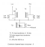
Do you mean something like this? It works.
The upper transformers are hi quality units, ex Martin Audio (UK) Concert Series. The lower unit is a bifilar wound unit, providing a 2:1
ratio. Below the xo freq, the 8 ohm load transforms to a 2 ohm load, which loads each chan at 4 ohms.
A very easy way to try a bass unit with fullrange drivers with a big difference in sensitivity.
Regards,
Geoff
Attachments
- Status
- This old topic is closed. If you want to reopen this topic, contact a moderator using the "Report Post" button.
- Home
- General Interest
- Everything Else
- Two Amps Powering One Driver