There is one cumbersome process to salvage whatever pictures of polar plots remains.Sadly the original files are no longer on PFM and the original recordings I don't think were published. Shame people use hosting for these things rather than uploading, but hey ho.
I think that there is a lot on tuning we can learn from this. As well as finding out that SP-10 owners were (damnit) right all along")
- In google images search 'Turntable Speed polar plots' or something similar to that.
- Select whatever images are shown in Pink Fish Media forum
- go to 'visit page' as well as 'visit images'
- copy part of filename with extension text in address bar
- Search that text in forum page of that particular image. which will give you reference to details and image in that post.
Where do we put stepper motors in various drive systems. Are they good comparatively ? A flatbed desktop scanner with stepper motor can scan an image 4800 dpi per inch, so are pretty much precise.
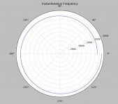
Great, at first sight it looks plausible, perhaps a bit noisy. I concur as to the range, and to check further I'd need to know the start time within the file: I used 10s as a start time and looked at 2 revolutions from there.This is what I got with the direct Hilbert transform method and simple two pole filtering at 100Hz. LD, I just grabbed 1.8 sec out of the middle of the file do your plots represent more than one rev? This is the MK4_XG-7001_WF_1 file recently posted. I used the library I wrote for LA which is a free download at Jan's site. Again one nice feature is that Python does not care about power of 2 FFT's.
Somewhere I still have the synthesised calibration files I used - I'll dig them out on link them in dropbox, they include noise rejection etc etc.
I think it's what I expect, and quietly makes me more optimistic that my detection method might be novel, perhaps........
Non-power of 2 support is very handy, but potentially expensive in terms of calc time......but then these are, presumably, short lengths. All good stuff !
LD
Last edited:
Great, at first sight it looks plausible, perhaps a bit noisy. I concur as to the range, and to check further I'd need to know the start time within the file: I used 10s as a start time and looked at 2 revolutions from there.
LD
I think I fixed the polar display problem, seems there is not as many methods for tick labeling in a polar plot. I think I can fake something. The noise comes somewhat from the fact that this method samples the instantaneous frequency at the same rate as the data. I post filtered the output to get this plot. I also noticed the second harmonic is at 10% and when I took another file from last week there was less close in noise.
I will keep playing and it is easy for me to repeat this starting at 10 sec. BTW there is virtually no performance hit if you stick to numbers with small prime factors, 44100, 96000, and 65536 are not very different in a modern FFT library. the FFT of 1000000 points and 1048576 point both return to the prompt instantaneously (also because the FFT library is totally compiled C++). A 6 digit prime however might take several minutes.
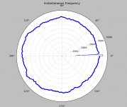
OK here's the same data as LD's, two revs starting at 10s. I noticed I have the scaling off a little because I tried to keep the plot less busy, easily fixed. I simply filtered the raw data twice this time, getting close.
EDIT - it looks like the tick marks are spaced twice as far apart as they should be no time left today to fix it.
EDIT - it looks like the tick marks are spaced twice as far apart as they should be no time left today to fix it.
Attachments
Last edited:

All sorts of clever processing in the scanner to get that resolution. Although for a belt drive you could use a stepper like a standard motor. Direct drive has its challenges due to the low speed of rotation, but they are solvable, and have been solved (at a price). The fun is getting that solution to a lower price. And at least we have the tools to analyse things now.Where do we put stepper motors in various drive systems. Are they good comparatively ? A flatbed desktop scanner with stepper motor can scan an image 4800 dpi per inch, so are pretty much precise.
EDIT: I realise that a sinusoidally commutated 2 phase BLDC and a microstepped stepper motor start to look very similar and TBH it's an area I need to do more research on, not least that if there is always a residual 'cogging' what is the best frequency to have this at.
Last edited:
Very nice that you can do that with a few lines of python, I'm impressed!
LD's plots have 0/360 deg at the top and the angles increase clockwise, which is more intuitive (at least to me).
I can probably rotate/flip the plot though I would first like to get his 0 equal to my 0, the start of a rotation is fairly arbitrary in any case. The default setup is the standard for vector notation I think.
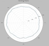
Decided to eat in tonight so I had time for a few more tweaks. This is a very old plot of a VPI HW-19. This is actually a before and after overlay of a 400Hz brickwall filtered data set. The noise immunity is pretty good.
Up to 34 lines of code now. Look forward to a comparison and or sanity check.
Up to 34 lines of code now. Look forward to a comparison and or sanity check.
Attachments
Last edited:
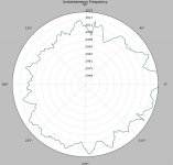
All good stuff, Scott.And here is the data set from yesterday, the glitch is a discontinuity at 0 from the IIR filter that I used to smooth the data. I was surprised that this technique is also fairly robust with respect to pops.
The range seems different between this plot and your linear plot in #356..... and also the range in your polar plot of the same dataset as mine is different I think - suspect a display scale issue, if you haven't already spotted it............?
I think a convention of rotation which follows platter direction, clockwise, is intuitive, and starting data at noon seems good as a convention, if that's possible ? That makes it far easier to compare results.
All on course - I'll up those calibration files once I find them...........
LD
All sorts of clever processing in the scanner to get that resolution. Although for a belt drive you could use a stepper like a standard motor. Direct drive has its challenges due to the low speed of rotation, but they are solvable, and have been solved (at a price). The fun is getting that solution to a lower price. And at least we have the tools to analyse things now.
EDIT: I realise that a sinusoidally commutated 2 phase BLDC and a microstepped stepper motor start to look very similar and TBH it's an area I need to do more research on, not least that if there is always a residual 'cogging' what is the best frequency to have this at.
The Phonosophie No.3 turntable that I have uses a stepper motor with a quadrature oscillator. Aren't stepper motor and synchronous motor the samething?
I posted a 3.15Khz sample tone, see post 30 of this thread (Phonosophie No.3 turntable with Thorens TP90 tonearm and Linn Arkiv B cartridge).
msdin
Stepper motors and synchronous motors are similar in design, but the shape of the pole pieces differs. Stepper motors are designed to move to a specific point, and have 'square' pole pieces, synchronous motors have more triangular pole pieces and are designed for continuous movement. This means that stepper motors tend to cog more than synchronous ones, and may need a more flexible belt
OK just seen this - presumably, that should fix the scale issue ?EDIT - it looks like the tick marks are spaced twice as far apart as they should be no time left today to fix it.
Scott, is it possible to place the ticks at 0.1% or 3Hz intervals, by convention, for consistency, and to display either 18 or 20 ticks or that equivalent range?
LD
It should be possible to drive the stepper with a custom non sinusoidal or rectangular waveform to reduce cogging. Once you are synthesising the drive waveform in software, this is not that hard to do....Stepper motors are designed to move to a specific point, and have 'square' pole pieces, synchronous motors have more triangular pole pieces and are designed for continuous movement. This means that stepper motors tend to cog more than synchronous ones...
The key parameter is that the coils and pole pieces should be closely matched.
Interesting. When I started researching this academic papers suggested that the pole:slot ratio was more important and the 4:12 chosen by technics for the SL-1200 is actually one of the worst for torque ripple. Now matsushita knew this and the high end japanese DDs all use a different ratio! Custom magnetics might be an interesting tweak.
Scott: Ignoring the fact it took you (mumble) years to get that compact at python that is a master class on how modern PCs where cpu, ram and disk are in excess can do amazing things quickly when you bolt all the right add-ons in
Scott: Ignoring the fact it took you (mumble) years to get that compact at python that is a master class on how modern PCs where cpu, ram and disk are in excess can do amazing things quickly when you bolt all the right add-ons in
Thing is, as one can see, unless there's a fault there isn't observable cogging in the SL-1200- at least as turns up as pitch variation.Interesting. When I started researching this academic papers suggested that the pole:slot ratio was more important and the 4:12 chosen by technics for the SL-1200 is actually one of the worst for torque ripple. Now matsushita knew this and the high end japanese DDs all use a different ratio! Custom magnetics might be an interesting tweak.
Scott: Ignoring the fact it took you (mumble) years to get that compact at python that is a master class on how modern PCs where cpu, ram and disk are in excess can do amazing things quickly when you bolt all the right add-ons in
But one could say the same for BDs, generally. Even modest DDs and BDs from the day typically can be very stable, unless there's a fault: other effects than motor drive typically dominate.
This, I think, is the 1st surprising observation obtaining from polar plots. Sure, there are plenty of examples of TTs with faults, often undiagnosed, but healthy TTs of good pedigree generally can't be separated by performance of the drive system type, IME.
LD
OK just seen this - presumably, that should fix the scale issue ?
Scott, is it possible to place the ticks at 0.1% or 3Hz intervals, by convention, for consistency, and to display either 18 or 20 ticks or that equivalent range?
LD
I already set 20 ticks up just need to shrink the font size a little to make it readable without blowing it up too much. Not all the axis labeling commands have correction for the polar projection built in but I know I can fix the theta axis labels somehow if even brute force changing their text.
- Status
- This old topic is closed. If you want to reopen this topic, contact a moderator using the "Report Post" button.
- Home
- Source & Line
- Analogue Source
- Turntable speed stabilty